BLUEHELIX MAXIMA
228 EN
cod. 3541U630 - Rev. 00 - 07/2020
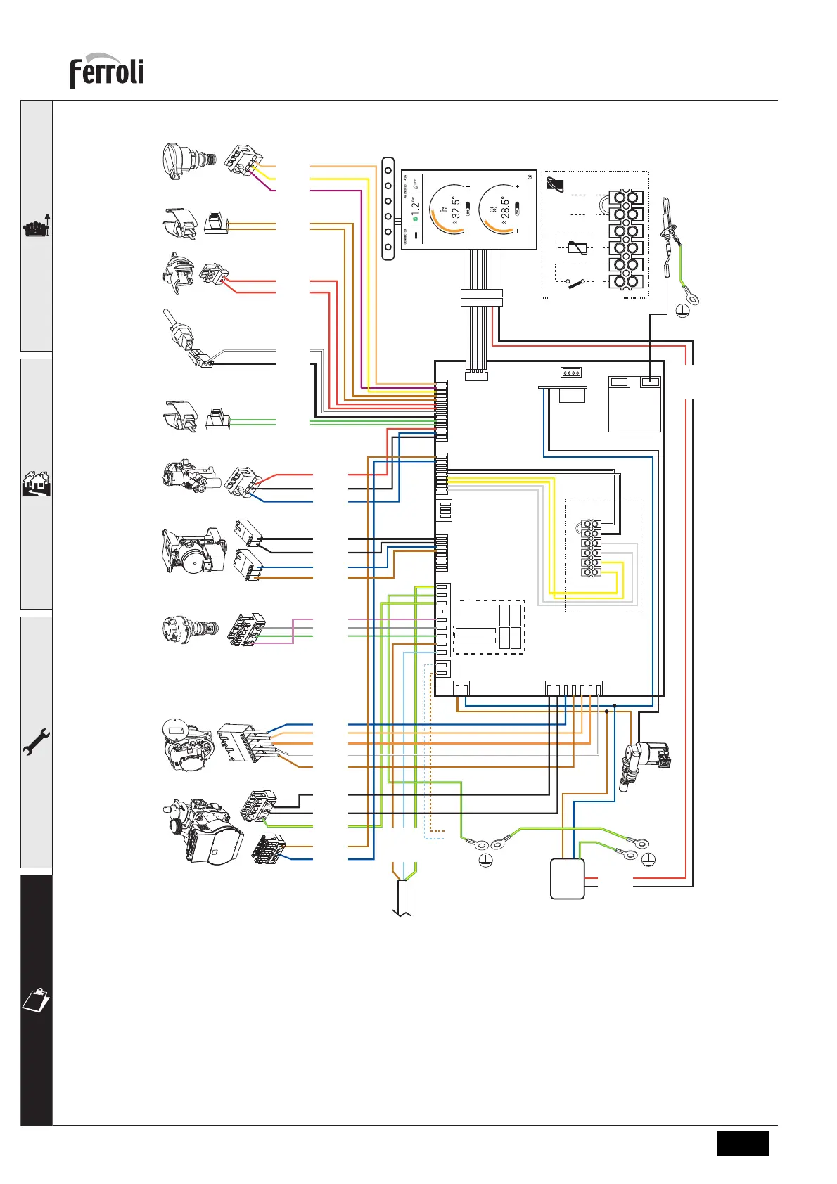
fig. 47- Wiring diagram
A
Attention: Remove the jumper on the terminal block before connecting the room thermostat or the remote
timercontrol.
To connect multiple zones of the plumbing system controlled by thermostats with voltage-free contact and to
use the timer control as a function of remote boiler controls, connect the voltage-free contacts of the zones to
terminals 1-2 and the timer control to terminals 5-6.
ALL CONNECTIONS TO THE TERMINAL BLOCK MUST BE WITH VOLTAGE-FREE CONTACTS (NOT
230V).
LC32
X03
X04
X05
X06
X07
X08
X02
X01
11
1
1
11
1
1
X09
X11
12345 6
terminal block
FUSE
3.15A - 250V
X04-8
X04-9
X04-1
230V
50Hz
GROUND
+24V.
GND
+24V.
GND
288
81
Power
box
240
LED
GROUND
1
GROUND
X08-7
X08-6
42
X08-2
X08-1
X08-3
294136
X08-14
X08-12
X08-13
X04-6
X04-7
X04-5
95
X01-5
X01-4
X01-7
X01-6
X01-3
16
X08-11
X08-10
186
X08-4
X08-5
3432
X07-1
X07-2
X04-3
X01-1
X01-2
X05-4
X05-3
X05-2
X05-1
44
X08-9
191
X08-8
139
138
A
3
4
5 6
1
2
terminal block
 Loading...