BLUEHELIX MAXIMA
227EN
cod. 3541U630 - Rev. 00 - 07/2020
4.5 Diagrams
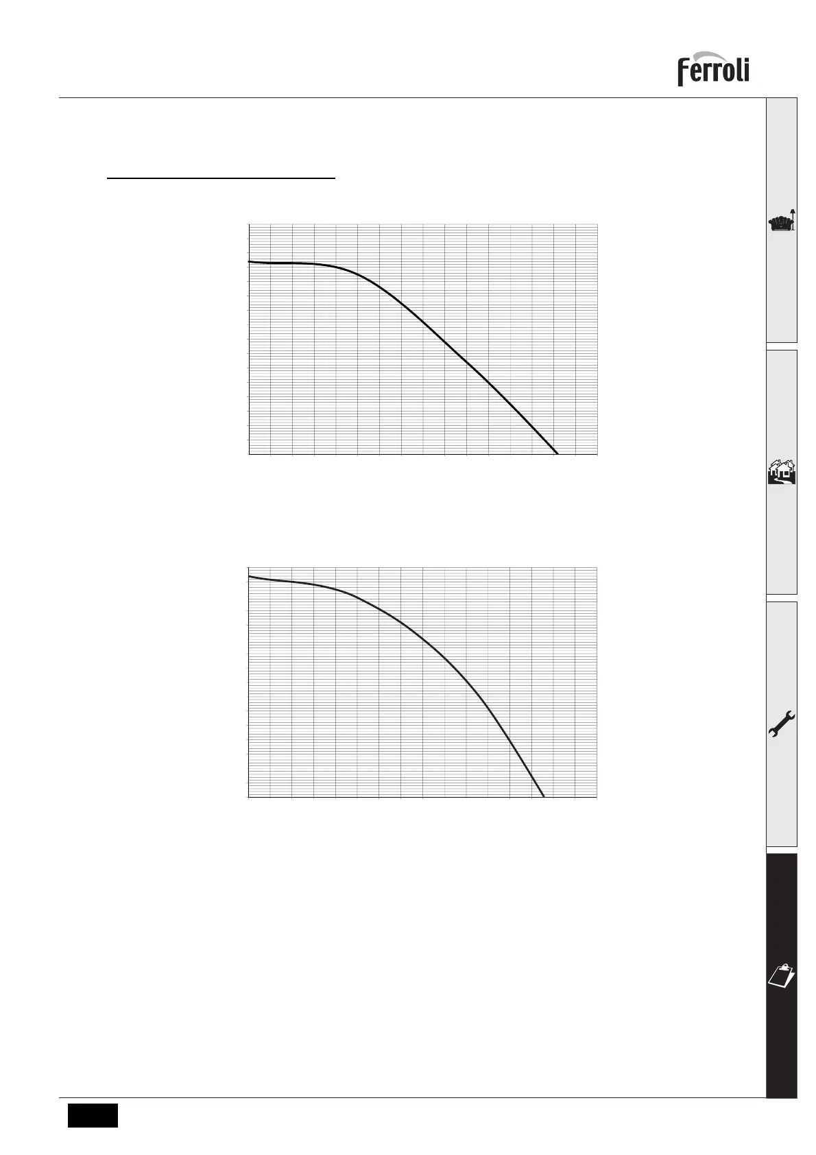
Residual head available for system
BLUEHELIX MAXIMA 24C and BLUEHELIX MAXIMA 28C
fig. 45- Residual head available for system
BLUEHELIX MAXIMA 34C
fig. 46- Residual head available for system
4.6 Wiring diagram
16 Fan
32 Heating circulating pump
34 Heating temperature sensor
42 DHW temperature probe
44 Gas valve
81 Ionization/ignition electrode
95 Diverter valve
136 Flowmeter
138 External probe (optional)
139 Remote timer control/Gateway
186 Return sensor
191 Fume temperature sensor
240 Filling solenoid valve
288 Frost protection kit
294 Pressure sensor
A ON/OFF switch (configurable)
0.0
0.5
1.0
1.5
2.0
2.5
3.0
3.5
4.0
4.5
5.0
5.5
6.0
6.5
7.0
7.5
8.0
0 0.1 0.2 0.3 0.4 0.5 0.6 0.7 0.8 0.9 1 1.1 1.2 1.3 1.4 1.5 1.6
H(mCA)
Q (m3/h)
0.0
0.5
1.0
1.5
2.0
2.5
3.0
3.5
4.0
4.5
5.0
5.5
6.0
6.5
7.0
7.5
8.0
0 0.1 0.2 0.3 0.4 0.5 0.6 0.7 0.8 0.9 1 1.1 1.2 1.3 1.4 1.5 1.6
H(mCA)
Q (m3/h)
 Loading...