4
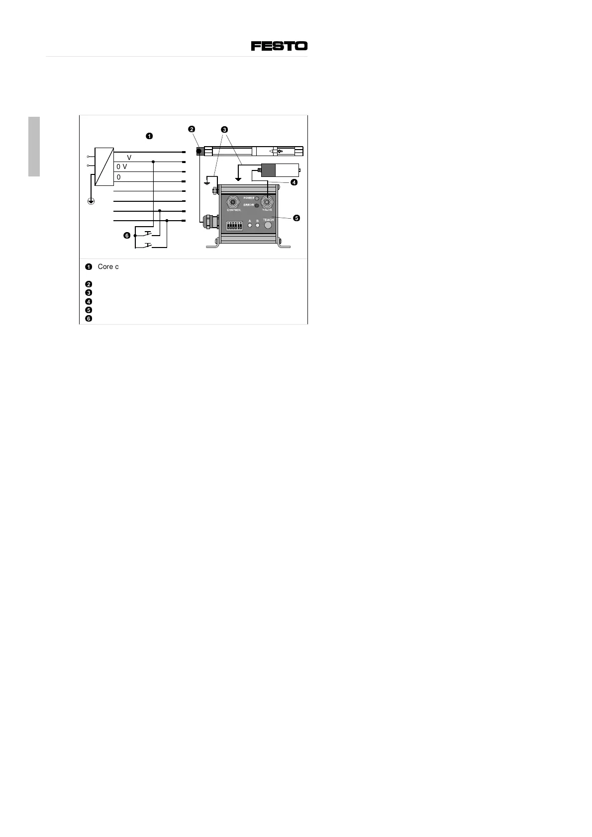
Installing the electrical components
Install the electrical components as shown in the diagram
below. Use only the original cables specified.
1
2
3
4
5
6
Core colours on the operating voltage cable and input/output
cable (type KSPC10-SPS-10)
Cable to linear potentiometer with cube plug
Earthing for MPYE-5-... and SPC-10
Valve cable (type KMPYE-...)
SPC-10
Push button for movement to A or B
Connect an earth cable with sufficient cable cross section to the
cylinder, if this is not fitted to an earthed machine stand.
1
2
4
5
6
3
24 V
24 V
0 V
0 V
Output A
Output B
Input B
Input A
white
brown
green
yellow
grey
pink
blue
red
1
2
3
4
5
6
7
8
English
SPC-10-...
16
9902c
 Loading...