10
InstallatIon
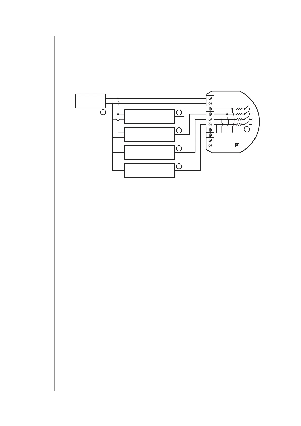
4.5: Connection with 0-10V analog sensors
The 2-wire analog sensor requires pull-up resistor.
You can connect up to 2 analog sensors to IN1/IN2 terminals.
1. Disconnect power.
2. Connect with the diagram below:
VDD
GND
OUT0-10V
0-10V
0-10V
0-10V
VDD
GND
OUT
GND OUT
GND OUT
12/24V DC
GND
IN3
IN4
IN1
GND
P
IN2
1
6
6
6
6
12V
7
Diagram 5: Example connection with 4 0-10V analog sensors
(1 – power supply, 2 – switch, 6 – 0-10V analog sensor, 7 – con-
gurable pull-up resistors)
3. Verify correctness of connection.
4. Power the device.
5. Add the device to the Z-Wave network.
6. Change values of parameters:
• Connected to IN1:
» Does not require pull-up: change parameter 20 to 0
» Requires pull-up: change parameter 20 to 1
• Connected to IN2:
» Does not require pull-up: change parameter 21 to 0
» Requires pull-up: change parameter 21 to 1
• Connected to IN3:
» Does not require pull-up: change parameter 22 to 0
» Requires pull-up: change parameter 22 to 1
• Connected to IN4:
» Does not require pull-up: change parameter 23 to 0
» Requires pull-up: change parameter 23 to 1