8
InstallatIon
IN1 – input connector for controlling OUT1 output
IN2 – input connector for controlling OUT2 output
IN3 – input connector for controlling OUT3 output
IN4 – input connector for controlling OUT4 output
OUT1 – output connector controlled by IN1 input (red LED color
recommended)
OUT2 – output connector controlled by IN2 input (green LED color
recommended)
OUT3 – output connector controlled by IN3 input (blue LED color
recommended)
OUT4 – output connector controlled by IN4 input (white LED color
recommended)
B – service button (used to add/remove the device)
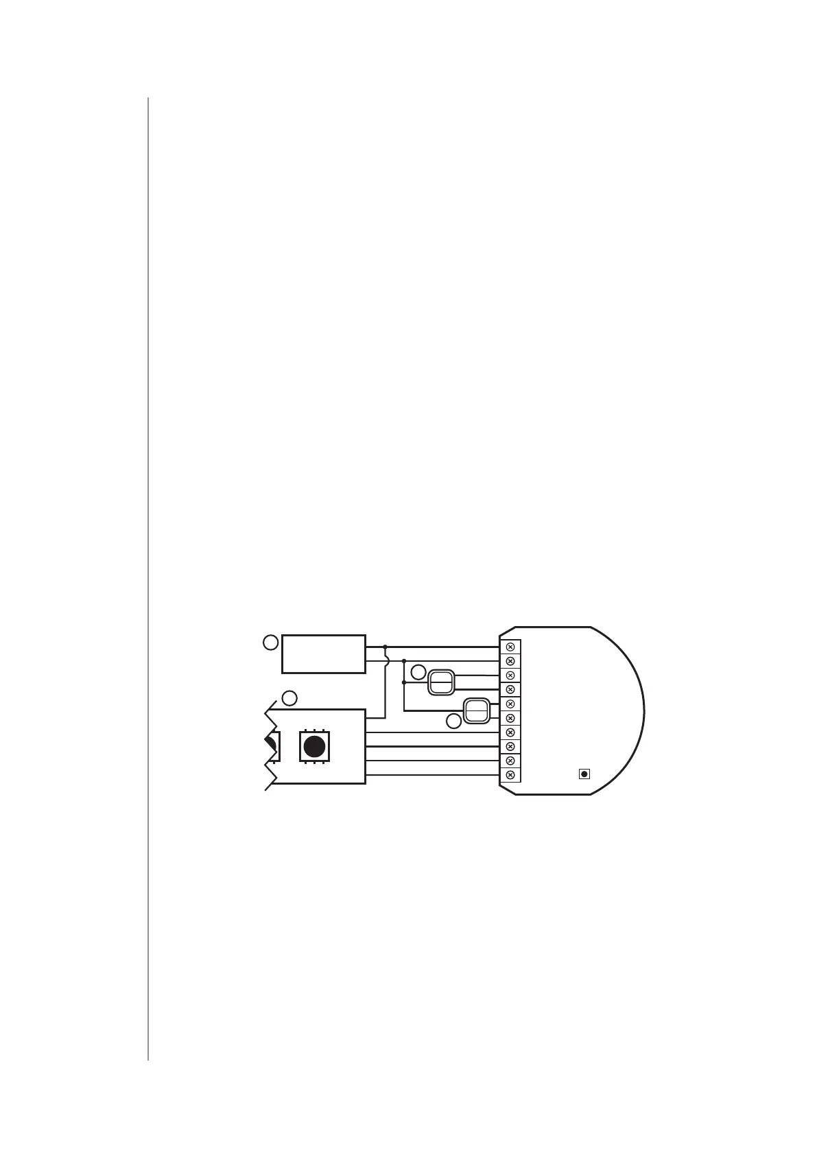
4.2: Connection with RGBW/RGB LED strip
We recommend connecting LED strip channels in the same order as
on the diagram (R - OUT1, G - OUT2, B - OUT3, W - OUT4).
If you want to connect RGB strip, use the same diagram, but do not
connect OUT4 channel.
1. Disconnect the power.
2. Connect with the diagram below:
12/24V DC
GND
12/24V
R
G
B
W
IN3
IN4
OUT1
OUT2
OUT3
OUT4
IN1
GND
P
IN2
2
2
1
3
Diagram 1: Example connection with RGBW LED strip
(1 – power supply, 2 – switch, 3 – RGBW LED strip)
3. Verify correctness of connection.
4. Power the device.
5. Add the device to the Z-Wave network.
6. Change values of parameters:
• Connected to IN1:
» RGBW: change parameter 150 to 0
» HSV and White: change parameter 150 to 1