4140
Error Message Cause Solution
Left Fiber Place
Error
The ber end-face is placed
on the electrode centerline.
Press RESET button, and reload the bers
to make sure that ber end face is placed
between V-groove and the centerline of
electrodes.
Right Fiber Place
Error
Press Motor Distance
Over Limit
The ber is not set correctly
at the bottom of the
V-groove, which results in
that the ber osets beyond
motor formation range.
Press the “RESET” button; correctly re-
position the ber at the bottom of the
V-groove.
Press Motor Error Motor might be damaged. Consult your nearest sales agent.
Search Fiber End
face Failed
The ber is not set
correctly at the bottom of
the V-groove.
Press the “RESET” button; correctly re-
position the ber at the bottom of the
V-groove.
Arc Failure
Arc discharge does not
occur.
Conrm the electrodes are in proper
position; Replace the electrodes.
Align Motor Distance
Over Limit
The ber is not set correctly
at the bottom of the
V-groove.
Press the “RESET” button; correctly re-
position the ber at the bottom of the
V-groove.
Search Fiber Clad
Failed
The ber is not set
correctly at the bottom of
the V-groove.
Press the “RESET” button; correctly re-
position the ber at the bottom of the
V-groove.
Fiber Border
Position Wrong
There’s dust or dirt on the
ber surface
Prepare the ber (stripping, cleaning, and
cleaving) again; clean the lens; redo [Dust
Check]
Unknown Fiber Type
There’s dust or dirt on the
ber surface
Prepare the ber (stripping,
cleaning, and cleaving) again.
Dierent ber types on two
sides.
Use an appropriate splice mode other than
AUTO splice mode to re -splice.
Non-standard optical bers
AUTO splice mode can only detect the
standard SM, MM, NZ bers.
Fiber Clad Over
Limit
Fiber edge is not located in
the camera range.
Adjust the ber position and perform “motor
calibration” .
Appendix B
During the splice operating process, if the error messages are shown on the screen,
please follow the solution precisely as shown in the list below. If it is not possible to
solve the problem, the splicer may require service by a qualied service center. In
this case, please contact sales agents.
Note:
A vertical line sometimes appears at the splice point when MM bers or dissimilar
bers (dierent diameters) are spliced. We call it as “Splicing line”. This does not
aect splice quality (such as splice loss and tensile strength).
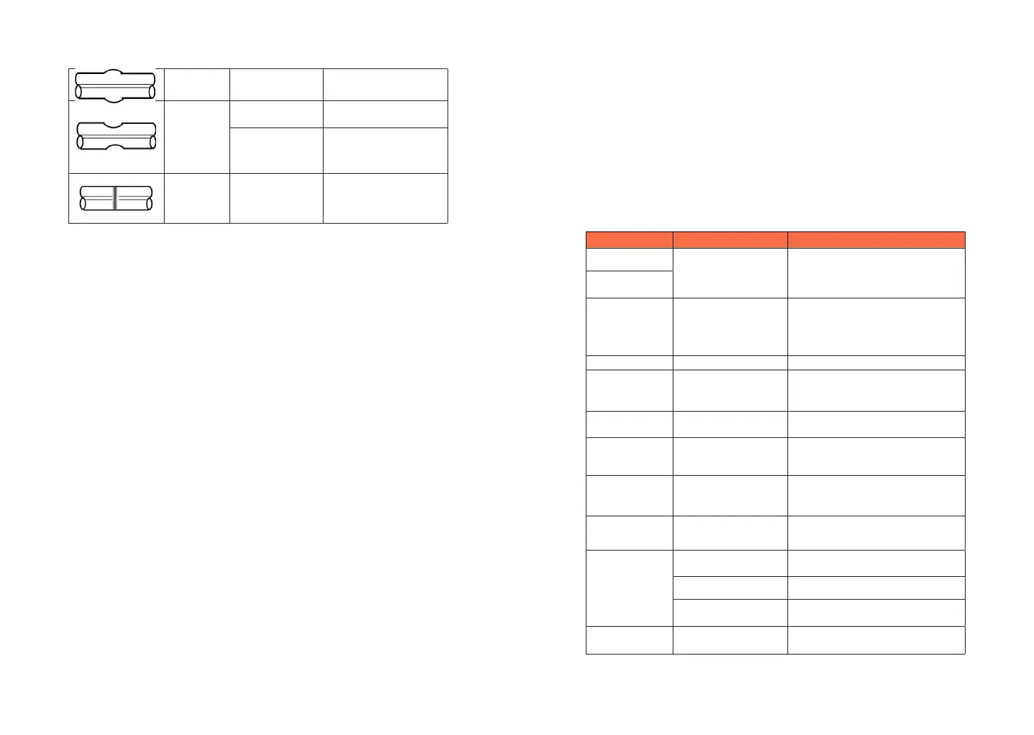
Fat
Fiber stung too
much
Decrease [Overlap] and
Perform [Arc Calibration].
Thin
Arc power not
adequate
Perform [Arc Calibration].
Some arc
parameters not
adequate
Adjust [Pre-fuse Power],
[Pre-fuse Time] or
[Overlap].
Splicing line
Some arc
parameters not
adequate
Adjust [Pre-fuse Power],
[Pre-fuse Time] or
[Overlap]
High Splice loss: Cause and solutions