Reproduction forbidden without Fibocom Wireless Inc. written authorization - All Rights Reserved
FIBOCOM L610 Series Hardware Guide Page 51 of 59
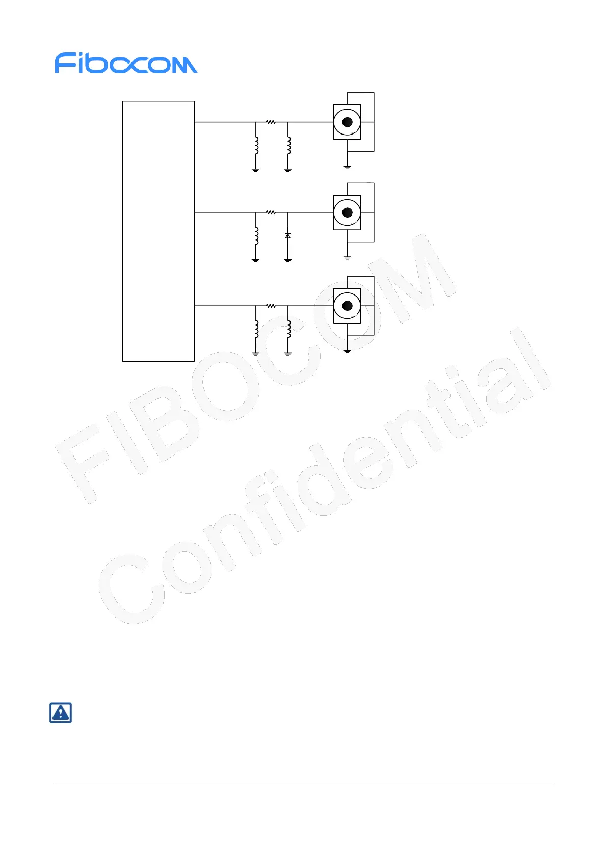
Figure 4-1 RF Reference circuit design
Make sure the characteristic impedance of the transmission cable is 50 Ω.
Since the antenna cable loss is less than 0.3dB, keep the PCB routing as short as possible.
PCB LAYOUT should be as straight as possible to avoid vias and layers, and avoid right-angle and
acute-angle routing.
PCB routing should have a good reference ground to avoid other signal line from approaching the
antenna.
A complete ground level is recommended as a reference ground.
Strengthen the connection between the ground around the antenna and the main ground.
ANT_WiFi/GNSS needs to add TVS to prevent ESD, recommended model: ESD9D5U-2/TR.
It is necessary to ensure that that distance between the main antenna and the WIFI/Bluetooth receive
antenna is appropriate. π type matching elements should be placed as close to the antenna as
possible.
ANT_MAIN needs to add TVS to prevent ESD, recommended model: ESDU5V0Y1.
ANT_GNSS without external power supply, using passive GNSS antenna.
If the customer requires an active GNSS antenna, use an external LDO supply depending on the
active antenna Type.
Note:
Refer to FIBOCOM Design Guide_RF Antenna for specific design details.
 Loading...