Reproduction forbidden without Fibocom Wireless Inc. written authorization - All Rights Reserved
FIBOCOM L610 Series Hardware Guide Page 45 of 59
noise of DCS1800 is severe. Therefore, the customer can choose the filter capacitance according to the
test results.
The position of the RF filter capacitor on the PCB should be as close to the audio device or the audio
interface as possible, and the layout should be as short as possible. The filter capacitor should be first
passed before reaching other connection points. The position of the antenna should be as far as possible
from the audio component and audio layout to reduce radiation interference. The power supply layout and
audio layout should not be parallel, and the power supply cord should be as far as possible from the audio
layout. Differential audio layout must follow the routing rules for differential signals.
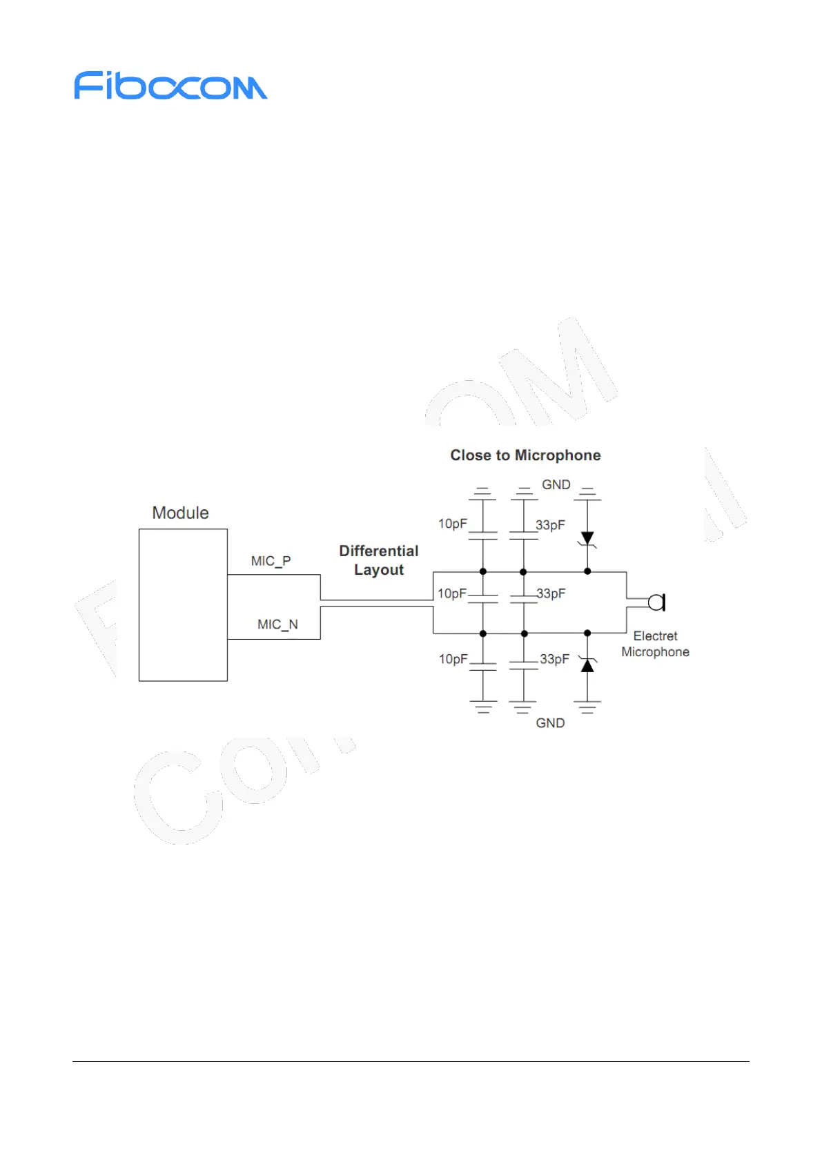
3.10.4 Microphone Interface Circuit
The MIC_P/MIC_N has provided the ECM bias voltage internal, and there is no need to add the bias
circuit external. The microphone reference circuit is shown in the following figure:
Figure 3-20 MIC reference circuit
 Loading...