Reproduction forbidden without Fibocom Wireless Inc. written authorization - All Rights Reserved
FIBOCOM L610 Series Hardware Guide Page 41 of 59
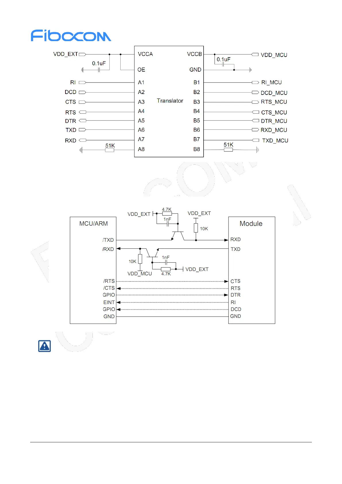
Figure 3-17 UART signal connection 1
Another level switching circuit is shown in the figure below. The input and output circuit design in the
following dashed part can refer to that in the solid line part, but pay attention to the connection direction.
Figure 3-18 UART signal connection 2
Note:
This level switching circuit is not suitable for applications with baud rates above 460Kbps.
3.7 Status Indicator
3.7.1 NET_MODE Signal
L610 modules provide three network indicator output signal interfaces.
 Loading...