PAGE/4 Doc.P/N06‐312
Rev.11/March2020
3.0 CONTAINERANDVALVEPREPARATION
3.1 TestandInspection
PROINERTinertgascontainerswillnotbefilledwithoutre‐testingifmorethan10yearshaveelapsedsincethedateof
thelasttestandinspection.
WARNING: PROINERTcontainercontentsareunderhighpressure.Neverattempttofillthecontaineruntilthe
contentshavebeendischargedandthepressuregaugereads0.
CAUTION: Careshouldbetakenwhenhandlingvalvecomponentstoavoiddamageofanykind.
3.2 ValveInstallationProcedure
Theproceduredetailedbelowdescribesthestepsnecessarytoinstallanewvalvetoacylinder:
Visuallyinspectcylinderthreadsandchaseanyburrsordebrisusinga1"NGTtap.
Vacuumallcylinderspriortovalveinstallationtoremoveanydebris.
PreparethePROINERTvalvewiththreewrapsof¾"wide,high‐densityPTFE
threadsealtapeontothe1"NGTmalethread.Wrapthethreadswithtape
clockwisewhenviewedfromthevalveinlet.Compressthetapeagainstthe
threadssecurelybyhand.
Usingabrush,applyGasoilaSS‐16Soft‐Setthreadsealantontothetaped
portionofthread.Applyenoughthreadsealanttocoverthefirst2‐3threads
ofthevalve(Figure3.2‐1).
Threadthevalveintothecylinderhand‐tightandthentightentoa
torqueof166to207lbf‐ft(225to280N‐m).
NOTE: InstallthevalveonthecylinderimmediatelyaftertheGasoila
threadsealantisappliedontothePTFEtapetopreventtheGasoilathreadsealantfromsettingpriortothe
valvebeinginstalledonthecylinder.
Checkforpropervalveinstallationwiththecylinder/valveengaugementgauge.Usethegaugetocheckthe
gapbetweenthecylinderneckbossandtheshoulderabovethe1"NGTthread(Figure3.2‐2).
o Valveisproperlyinstalledifthe“max/no‐go”sideofthegaugecannotfitinthe
gapANDthe“min/go”
can.
o Valveisimproperlyinstalledifthe“max/no‐go”sideofthegaugecanfitinthegapORthe“min/go”
cannot.
Thecontainerisnowreadyforfilling.
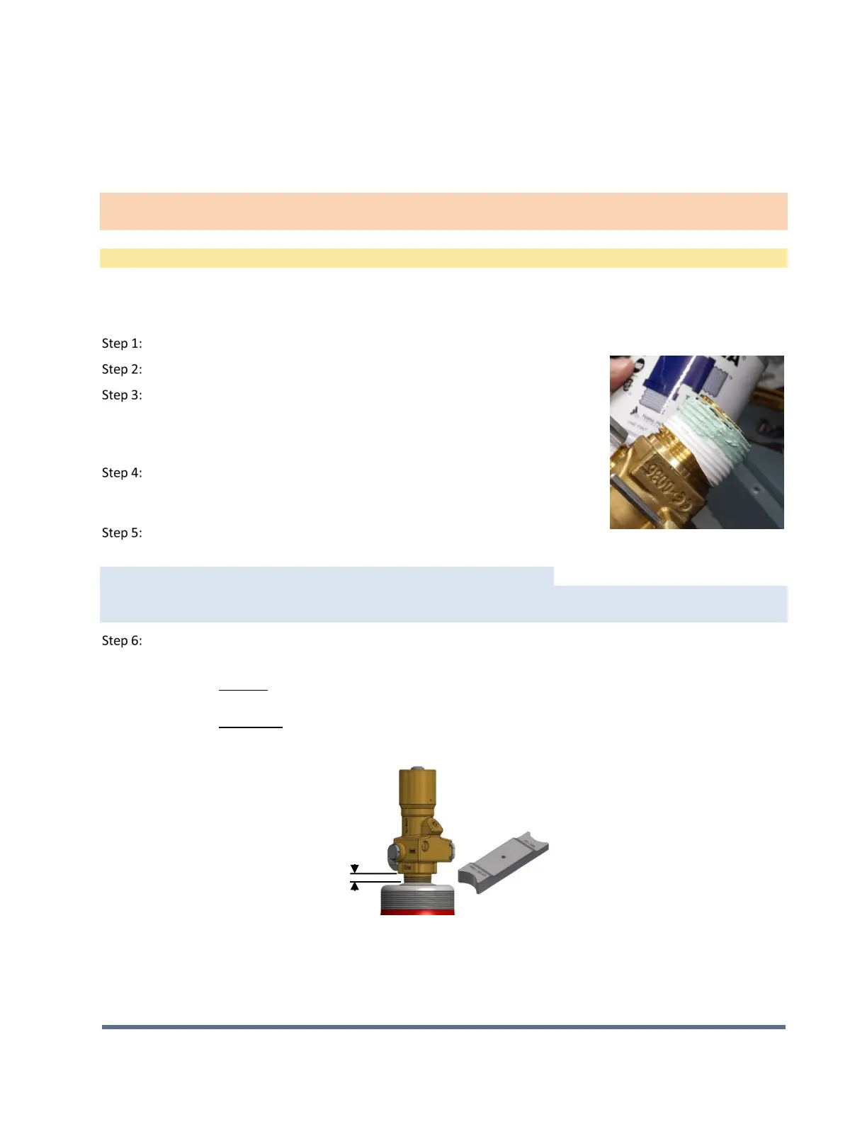
Figure3.2‐2CylinderValveEngagementGauge
Check
gap
using
both
Cylinder/Valve
Engaugement
Gauge
Figure3.2‐1GasSealantonThreads