TECHNICAL DATA
TECHNICAL DATA
U/M
[KMS]
GL Pro GxL Pro
GXL Pro
Orbital
Nominal input power [IEC 60335-2-72; IEC 62885-9] kW 0,72 0,78 0,68
Productivity theoretical m
2
/h 1300 1600 1600
Working width [IEC 62885-9] mm 355 430 430
Total width of brushes [IEC 62885-9] mm 1x355 1x432 -
Total width of the abrasive pad [IEC 62885-9] mm - - 1x432
Nominal power of brush motor/s [IEC 62885-9] W 440 500 400
Single brush rpm rpm 197 140 -
Number of oscillations of the abrasive pad rpm - - 2300
Maximum pressure exerted by the brush head on the oor N/cm
2
0,42 0,55 0,55
Maximum gradeability during work (GVW) % 2 2 2
Drying track [IEC 62885-9] mm 420 510 510
Squeegee width mm 440 516 516
Nominal power of vacuum motor(s) [IEC 62885-9] W 280 280 280
Maximum vacuum [IEC 62885-9; IEC 60312-1] KPa 6,9 6,8 6,8
Solution tank l 15 25 25
Recovery tank l 17 27 27
Machine dimensions during transport [IEC 62885-9] mm 457 490 490
Machine dimensions (length - height - width) mm
765
1110
490
895
1215
530
895
1215
530
Battery compartment dimensions (length - height - width) mm
215
195
270
245
250
290
245
250
290
Machine net weight [IEC 62885-9] kg 52,5 68 68
Machine weight during transport [IEC 62885-9] kg 73,5 105 105
GVW [IEC 60335-2-72; IEC 62885-9] kg 84 130 130
Sound pressure level in operator seat [ISO 11201] (L
pA
) dB 61,4 <70 <70
Sound power level [IEC 60335-2-72; IEC 62885-9; ISO 3744] (L
wA
) dB 73,9 <80 <80
Uncertainty K
pA
dB ±1,5 ±1,5 ±1,5
Hand-arm vibrations [IEC 60335-2-72; IEC 62885-9; ISO 5349-1] m/s
2
0,48 0,77 0,77
Vibration measurement uncertainty ±4% ±4% ±4%
IP test [IEC 60335-2-72; IEC 60529] IP 23 IP 23 IP 23
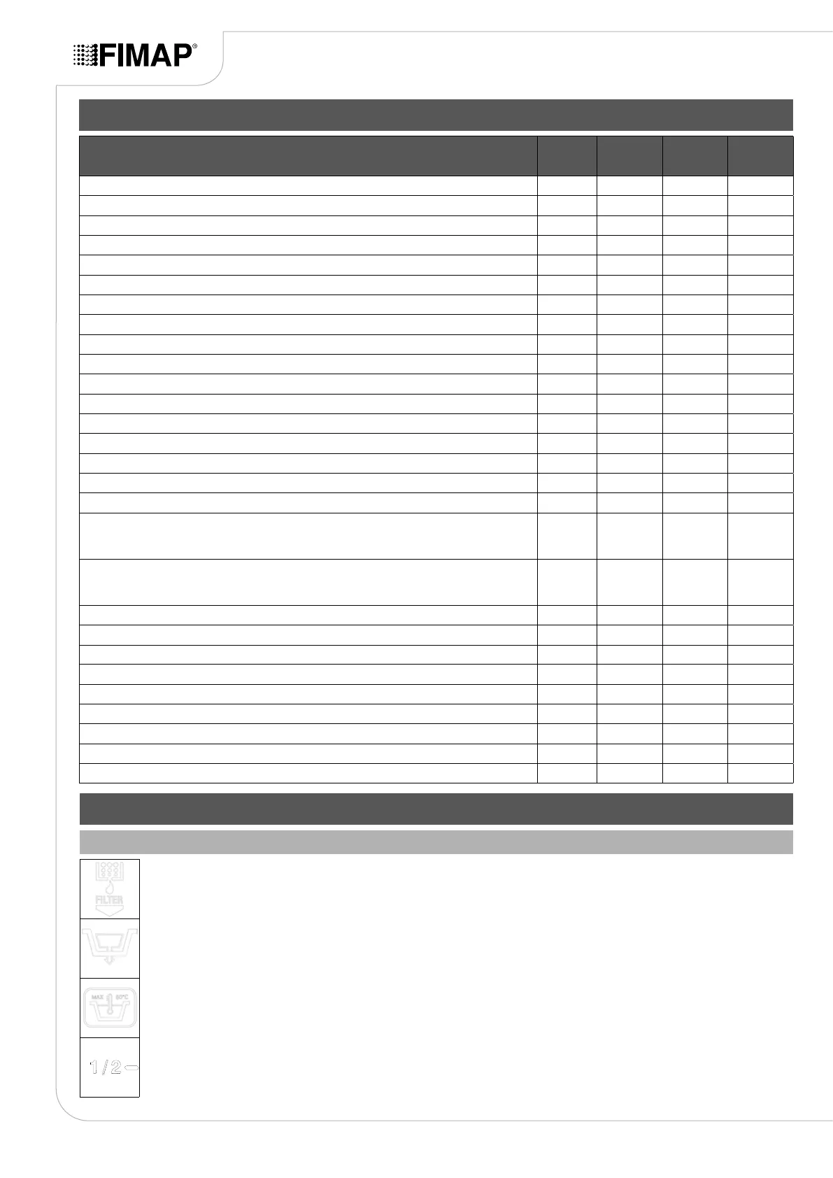
SYMBOLS USED ON THE MACHINE
Filter body position symbol:
Applied to the front of the machine to indicate the position of the solution tank lter.
Recovery tank drainage hose symbol:
Applied to the left-hand side of the machine to identify where to insert the dumping system tube for the solution tank.
Symbol for maximum temperature for lling the solution tank:
Located on the front of the machine to indicate the maximum temperature of the water for lling the solution tank safely.
Solution tank lling symbol:
Located on the left side of the machine's solution tank to indicate the amount of water or detergent solution in the tank. The symbol
on the side indicates that the tank is full to about a half of its capacity.
SYMBOLS AND LABELS USED ON THE MACHINE
8