EN
60
Follow the procedure below to route all the requested cables:
ATTENTION – A The installation must be performed by
qualified installers and/or licensed electricians in accordance
with the existing regulations in the country of installation and
in accordance of all safety rules for performing electrical
works. The customer has civil liability for the qualification and
mental or physical state of the personnel who interact with
the equipment. They must always use the personal protective
equipment (PPE) required by the laws of the country of
destination and whatever is provided by their employer.
ATTENTION – A Before carrying out any operation, check
that any external AC switch downstream to the inverter (grid
side) are in OFF position applying LOTO procedure on it.
• Use the key tool (provided with the installation kit contained in
the wiring box package) to open the three cover quarter cam-
locks (05) following the proper rotation as shown in the related
silkscreens on the Wiring box cover (07).
NOTE – D Only for -S2, -SX2, SY2 versions: Set the wiring
box AC disconnect switch (09) to OFF position; otherwise it
will not be possible to open the wiring box cover (07).
• Open the wiring box cover (07) and use the cover support
brackets (14) to lock the cover (07) in open position.
ATTENTION – A Pay attention to properly secure the cover
support brackets (14) in order to avoid falling of the cover!
• Remove the AC protective shield (27) by removing the M5 screw.
27
Depending on the ground connection method (internal (25) or
external (10)) follow the procedures described below:
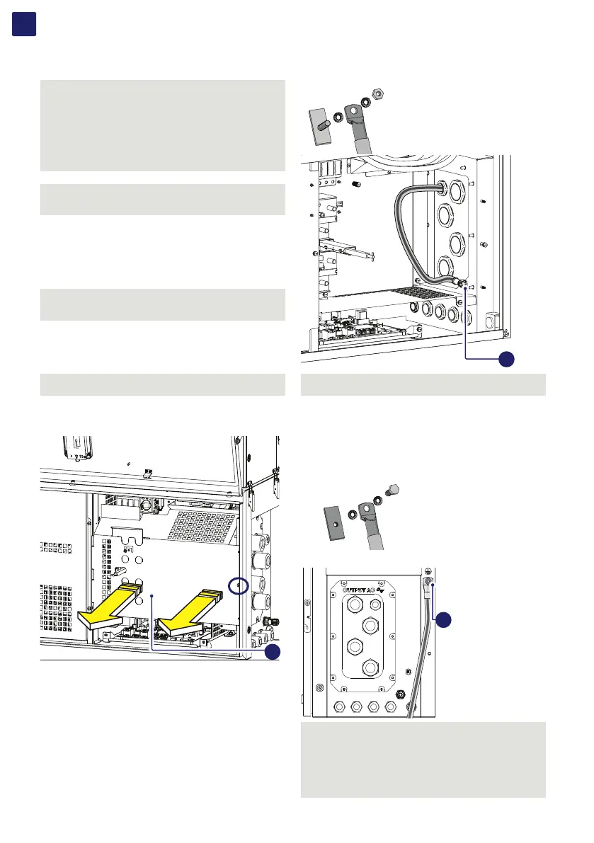
5.9.5.1 Internal ground connection
• Pass the protective earth cable through the proper cable gland
(23) on the AC panel.
• Fix the protective earth cable lug to the protection earth
connection point (int.) (25) using the washers and nut pre-
installed on the M10 stud, as shown in the following diagram:
1 = serrated washers
2 = cable lug
3 = serrated washers
4 = M10 nut
1
2
3
25
ATTENTION – A The cable lug must be installed with a
tightening torque of 21Nm.
5.9.5.2 External ground connection
• Fix the protective earth cable lug to the protection earth
connection point (ext.) (10) (this is the same thread for handles)
using the washers and M8 bolt provided in the wiring box
component kit, as shown in the following diagram:
1 = serrated washers
2 = cable lug
3 = serrated washers
4 = M8 bolt
10
ATTENTION – A The cable lug must be installed with a
tightening torque of 15.2 Nm.
ATTENTION – A Before connecting the inverter to AC or DC
sources use a suitable multimeter to test the conductivity
of the earth connections between the protection earth
connection point (ext.) (10) and a handles thread on the
housing of power module.