EN
74
observed as regards cable cross-section (it only needs to comply
with the sizing requirement for passing cables through the cable
glands and the terminal connector).
The external switch used for Remote ON/OFF should be rated for
DC low voltage, low current application (the minimum switching
current capability should be 1mA or lower).
READ THE MANUAL – E For further information regarding
the configuration and use of the Remote control terminal
block, please refer to the user manual.
5.11.7 Configurable Relay connection (ALARM
and AUX)
The inverter is equipped with 2 configurable relays terminal blocks
(33) with configurable activation.
It can be connected with normally open contact (being connected
between the NO terminal and the common contact C) and with
normally closed contact (being connected between the NC
terminal and the common contact C).
J2 X1
X2
S5S4
J7
J1
J5 J6
1
2
1
8
7
432
N.C N.OC
N.C. N.O.C
AUX
ALARM
33
Different types of devices (light, sound, etc.) can be connected to
the relay, provided they comply with the following requirements:
ALARM and AUX terminal block requirements
Alternating current
Maximum Voltage: 160 Vac /
Maximum Current: 6 A
Direct current
Maximum Voltage: 30 Vdc /
Maximum Current: 3 A
Cable requirements
Conductor cross-section: from 0.08
to 1.3 mm²
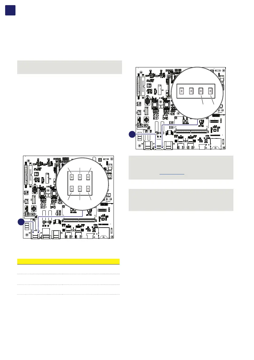
5.11.8 Demand Response Mode 0 (AS/NZS
4777.2)
Where requested by the AS/NZS 4777.2 standard, it’s possible
to use the remote terminal block (37) for the Demand Response
Mode 0 (DRM0) functionality.
The terminals to be used to connect the inverter to the distribution
grid are R2 and RTN.
J2 X1
X2
S5S4
J7
J1
J5 J6
1
2
1
8
7
432
37
NOTE – D AS4777: If DRM0 support is specified, the inverter
may only be used in conjunction with a the FIMER DRM0
Interface.
NOTE – D Visit www.fimer.com for more information on the
DRM0 interface.
ATTENTION – A In case of the DRM0 function is activated
without the proper wiring of the remote terminal block (37),
the inverter will no longer be able to connect to the grid. For
further information regarding the DRM0 function refer to the
AS/NZS 4777 standard.