EN
64
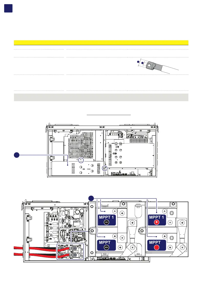
5.10.1.3 Connection of inputs
To carry out the connections, the cables must be passed through the DC cable glands (18).
Connection of DC cables is made on the DC input connection busbar (17).
The bolts on the DC input connection busbar (17) accepts cable lugs as per the following table:
DC input cable
Cable diameter range 19 - 28 mm
Conductor cross section
min. 50mm
2
(in case of 2 couples of DC cables)...max 185mm
2
min. 90mm
2
(in case of single couple of DC cables)...max 185mm
2
Cable lug dimensioning
for M10 Stud
a = 10.5 mm (min)
b = 40 mm (max)
b
a
Conductor material copper or aluminum
ATTENTION – A The DC input connection busbars (17) are in copper tin-plated; therefore if aluminum cables are used, the correct
coupling with the copper bars must be guaranteed by using appropriate bi-metallic cable lug.
In order to connect the DC input cables performs the procedure as follow:
• Open the wiring box front cover (07) (refer to paragraph “Opening the wiring box cover”)
• Remove the internal DC Protective shield (60) by removing the two M5 screws.
60
• Unscrew the DC cable glands (18)
• Introduce the cables
• Install the cable lugs on the cables
• Connect the DC cables to the busbars (17) with a tightening torque of 25 Nm. During this operation connect the cables with the right
polarity and MPPT.
MPPT 1
–
MPPT 1
+
MPPT 2
+
MPPT 2
–
17
• Once connection to the DC input connection busbar (17) has been completed, retighten the cable gland firmly (8.0 Nm torque) and
check seal.
• Re-install the DC protective shield (60) by using the M5 screws previously removed (torque of 3 Nm).