145
000761AG-F
8 - Maintenance
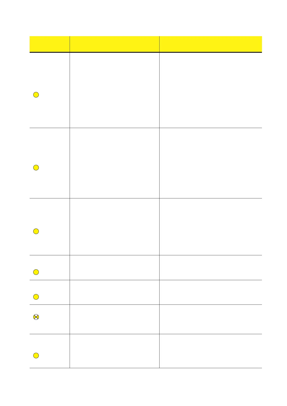
- Error code
- Error message
- Warning
Name of Alarm and Cause Solution
- W003
- Grid Fail
-
Yellow LED
Parameters of grid voltage outside range:
This error signal occurs when during the inverter's
normal operation the grid parameters exceed the
limits set by the operator:
- Grid voltage absent (after the signal the inverter
goes to "Missing Grid")
- Unstable grid voltage (values too low or too high)
- Unstable grid frequency
• Check the grid voltage on the inverter.
- Should it be absent, check for absence of grid voltage on the
supply point.
- If, on the other hand, the voltage tends to rise (when the
inverter is connected) there is high line or grid impedance.
• Check the grid voltage also on the supply.
- If it is high, it means that there is high grid impedance. In this
case, ask the operator to adjust the grid voltage. If the opera
-
tor authorises a change to the inverter's parameters, agree the
new limits with customer assistance
- If the voltage at the point of supply is much lower than that
measured on the inverter, it is necessary to adjust the line
(inverter-contactor).
- If the voltage and the grid frequency come back within the
limits (also when the inverter is connected to the grid), contact
customer assistance
- W004
- Grid OV
-
Yellow LED
Grid overvoltage:
This error signal occurs when during the inverter's
normal operation the grid voltage exceeds the maxi
-
mum limit set by the operator.
• Check the grid voltage on the inverter.
If the voltage tends to rise (when the inverter is connected),
there is a problem of high line or grid impedance.
• Check the grid voltage also on the supply.
- If it is high, it means that there is high grid impedance. In this
case, ask the operator to adjust the grid voltage. If the opera
-
tor authorises a change to the inverter's parameters, agree the
new limits with customer assistance
- If the voltage at the point of supply is much lower than that
measured on the inverter, it is necessary to adjust the line
(inverter-contactor).
- If the voltage and the grid frequency come back within the
limits (also when the inverter is connected to the grid), contact
customer assistance
- W005
- Grid UV
-
Yellow LED
Grid undervoltage:
This error signal occurs when during the inverter's
normal operation the grid voltage exceeds the mini
-
mum limit set by the operator.
• Check the grid voltage on the inverter.
• Check the grid voltage also on the supply.
- If it is high, it means that there is high grid impedance. In this
case, ask the operator to adjust the grid voltage. If the opera
-
tor authorises a change to the inverter's parameters, agree the
new limits with customer assistance
- If the voltage at the point of supply is much lower than that
measured on the inverter, it is necessary to adjust the line
(inverter-contactor).
- If the voltage and the grid frequency come back within the
limits (also when the inverter is connected to the grid), contact
customer assistance
- W006
- Grid OF
-
Yellow LED
Grid over-frequency:
This error signal occurs when during the inverter's
normal operation the grid frequency exceeds the
maximum limit set by the operator.
• Check the grid frequency in the inverter.
• Check the grid frequency also on the supply:
- If the voltage and the grid frequency come back within the
limits (also when the inverter is connected to the grid), contact
customer assistance
- W007
- Grid UF
-
Yellow LED
Grid under-frequency:
This error signal occurs when during the inverter's
normal operation the grid frequency exceeds the
minimum limit set by the operator.
• Check the grid frequency in the inverter.
• Check the grid frequency also on the supply:
- If the voltage and the grid frequency come back within the
limits (also when the inverter is connected to the grid), contact
customer assistance
- W010 *
- Fan Fail
-
Flashing yellow
LED
*not visualised on
display
Fan Fail:
This error occurs when there is a malfunction in the
fan/fans inside the inverter.
• Error inside the inverter and cannot be checked externally.
- If the alarm repeats persistently, contact customer assistan
-
ce.
- W011
- Bulk UV
-
Yellow LED
Low “Bulk” voltage (DC-DC circuit):
The alarm (which is a warning and not an error) is
generated when the voltage at the heads of the bulk
capacitors does not reach the threshold for the opera
-
tion of the inverter (internal unchangeable threshold).
• Raise the value of the activation voltage (Vstart) so as to
have sufcient power from the PV generator at the time of the
inverter's grid connection.
• Check the input voltage on the inverter.
- If it does not exceed Vstart, check for the presence of suf
-
cient irradiation and the correct composition of the system.
- If it exceeds Vstart, contact customer assistance.