80
000872BG-F
5 - Installation
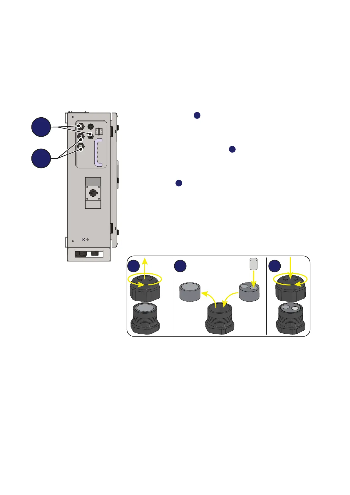
Connections to the communication and control board
The communication and control signals are connected to the commu-
nication and control board inside the wiring box. in particular, on the left
side of the DC wiring box, there are:
- 2 ethernet cable glands
12
(one PG21 and one PG16). The two cable
glands can be used for the daisy-chain connection (in / out) of inverters
present on the system. The ethernet connection can be used to monitor,
congure, and update the rmware remotely and is made on the dedica
-
ted connectors on the interposer board
50
.
- 2 cable glands
13
(PG21 ) that can be used to reach the termi-
nals / connectors on the communication and control board. Each
cable gland accepts a cable (from 13 mm to 18 mm diameter).
As an alternative to each cable gland, the two-hole gasket (supplied) can
be installed, which accepts two cables with a diameter of 1.5 to 6mm; If
a seal hole is not to be used, it is necessary to install a plug (supplied
plastic cylinder) to ensure the inverter’s sealing.