83
000872BG-F
5 - Installation
Serial Communication connection - Slave (RS485-1, RS485-2)
Be advise that automatic settings of network parameters at the turning on, embedded log-
ging capability, automatic logger free transferring of data to Aurora Vision Cloud and remote
rmware update are provided over TCP/IP (Ethernet and/or Wi-) bus only.
The use of the inverters over the RS485 line is recommended in case of monitoring and con-
trolling by using third party RS485 control systems.
The connection of the inverters over this RS485 line is recommended for replacement of
already installed old model of inverters or service purpose only.
- RS485-1 serial communication line.
The communication protocol can be set as “Aurora” (proprietary com-
munication protocol) or Modbus RTU (FIMER protocol).
This port must be used for rmware upgrading (locally or remo-
tely through the FIMER monitoring devices)
When connecting the FIMER monitoring devices, the RS485-1 line must be used
- RS485-2 serial communication line.
The communication protocol can be set as “Aurora” (proprietary com-
munication protocol), Modbus RTU (FIMER protocol) or Modbus RTU
(Sunspec protocol).
Cables connecting the RS485 line may use two different types of con-
nection:
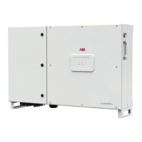
• Connection of the conductors using the terminal connectors
53
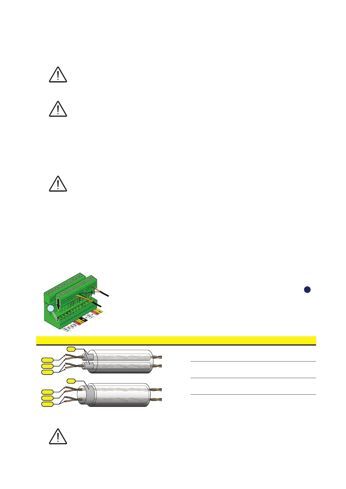
For long distance connections, the connection on terminal connector
is preferable using a shielded twisted pair cable with characteristic
impedance of Z0=120 Ohm like the one shown on the following table:
Signal Symbol
-T/R
+T/R
RTN
-T/R
+T/R
SH
RTN
Positive data RS485 (-1 or -2) +T/R
Negative data RS485 (-1 or -2) -T/R
Reference RTN
Screen SH
Shield continuity must be provided along the communication line using the SH terminal and
must be grounded at a single point.
RS485-2
RS485-1
IN
OUT
IN
OUT
(A)
(B)
(A)
(B)
RS485-1
RS485-2
57
56
53