FireClass Panels and Repeaters Connecting the CUI repeater RBus wires
Installation Guide Doc. version 2.0 20
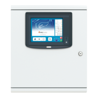
Fig. 15: CUI - Colour User Interface (557.202.919)
1– TB1
2– TB2
3– TB3
4– TB4
5– DC-DC converter position (If used for repeater.Plug into socket SK1 for repeater version).
6– Link L3 fit 2-3 if no DC-DC converter
7– Link L4 fit 1-2 if no DC-DC converter
8– X900 - 20 way ribbon cable connection to FC-FI/FC-FI-1
9– X204 - Boot-mode link. Link 1-2 normal run mode. Link 2-3 bootloader mode.
10–X200 - Watchdog link. Link 2-3 normal run mode. Link 1-2 watchdog disabled mode.
11–Zonal LEDs
12–Keyswitch
13–CON6 - 120R termination on RS485 comms. Link 2-3 to add 120R termination.
14–CON5 - 120R termination on RS485 comms. Link 2-3 to add 120R termination.
15–S1 DIP switch - Used to set the RBUS address and Baud rate. 1-4 RBUS Address. 5-6 Baud Rate select. 7-8 Future Use