17 Installation Guide Doc. version 2.0
Mounting CUI repeater panels FireClass Panels and Repeaters
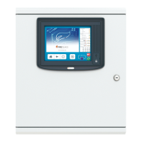
8 Mounting CUI
repeater panels
Complete the instructions in the following sections to
mount a FC32DR DC colour user interface (CUI)
repeater. For FC32AR repeaters, see section 5.1, “Con-
necting the mains cable and protective earths in FC600
series panels and AC repeaters” on page 11.
8.1 Connecting the CUI repeater
DC supply cabling
DC colour user interface (CUI) repeaters are powered
from the control panel. To connect the repeater DC
supply cabling, complete the following steps:
1 Identify suitable DC supply wire. Strip off the
insulation to leave a few millimetres of bare wire
ends.
2 At the control panel feed the wire into the housing
through a suitable knockout, using a gland if
necessary.
3 Note which colour conductor is connected to which
terminal on the panel to the 24V & 0V.
4 At the CUI repeater feed the supply cable through a
suitable knockout, using a gland if necessary.
5 At the CUI repeater there are two RBUS
connections, RBUS_L and RBUS_R, which are left
and right channels. Connect the 24V & 0V to the
appropriate terminal block.
6 For the RBUS_L use terminal blocks TB1 & TB2 and
RBUS_R use terminal blocks TB3 & TB4. As shown
in Table 2.
For the locations of the terminal blocks on the CUI
repeater, see items 1 to 4 in Fig. 13.
7 Connect the 24V & 0V to the appropriate terminal
blocks on the CUI repeater, matching the colours to
the terminals.
8.2 Connecting the CUI repeater
RBus wires
1 Wire the "control panel end" of the RBus wires into
their connector, XT1 on the FC-FI labelled LEB/
RBUS, A, B and GND. The connector is similar to the
loop connector.
2 Feed these wires out of the control panel through a
suitable knockout using a gland if necessary.
3 For RBUS_L use terminal blocks TB1 and TB2. For
RBUS_R use terminal blocks TB3 andTB4, as shown
in Table 2.
4 Double-check whether an EOLR resistor needs to be
fitted. There are links on the CUI repeater to add
120R termination on the RBUS. Link pins 2 and 3 on
the 3-pin connectors CON5 & CON6 to add this
PCB label Function
TB1 RBUS Left connections
for repeater CUI
Pin1 - CHASSIS
Pin2 - 0V
Pin3 - +24V DC
Table 2: Terminal block information
TB2 RBUS Left connections
for repeater CUI
Pin1 - RS485 NET REF
Pin2 - RS485 B
Pin3 - RS485 A
TB3 RBUS Right connections
for repeater CUI
Pin1 - CHASSIS
Pin2 - 0V
Pin3 - +24V DC
TB4 RBUS Right connections
for repeater CUI
Pin1 - RS485 NET REF
Pin2 - RS485 B
Pin3 - RS485 A
PCB label Function
Table 2: Terminal block information