Install the shelf clips into the shelf pilasters (front and back) at the desired
shelf level. Install the shelves in the cabinet onto the clips.
Note Maximum shelf load is 100 lbs (45.4 kg) per shelf.
s
Note On units having the optional 5 inner door option, refer to the
instructions accompanying the inner door kit.
s
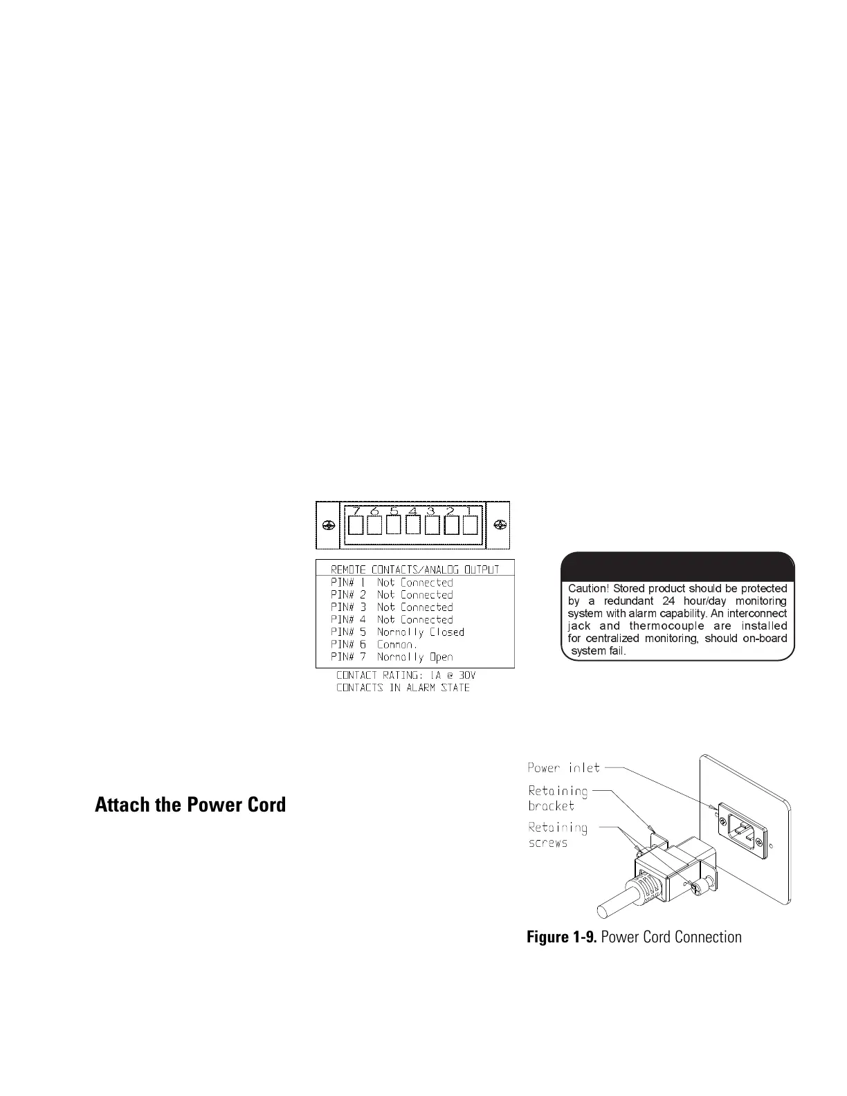
See Figure 1-2 for the location of the remote alarm contacts. The remote
alarm connector is located in the parts bag provided with the manual. It
must be installed if connecting the freezer to an alarm system. After
installing the wiring from the alarm system to the connector, install the
connector to the freezer microboard and secure with the two screws
provided. The remote alarm provides a NO (normally open) output, a NC
(normally closed) output and COM (common). The contacts will trip on a
power outage, high temperature alarm or low temperature alarm. They aill
also trip on high stage, control probe or microboard failure. Figure 1-8
shows the remote contacts in alarm state.
Insert the power cord into the
power inlet module. Place the
retaining bracket (P/N 195763)
over the connector. Tighten
retaining screws to secure.
Isotemp Basic 1-5Fisher Scientific
Section 1
Installation and Start-Up
Install the Shelves
Remote Alarm Contacts
Figure 1-8. Remote Alarm Contacts