Lit. No. 94866/94867 11 June 1, 2002
Hydraulic Unit Installation
Recommended sequence of installation is as follows:
1. Pump (not provided).
2. Install hydraulic reservoir.
3. Install cab control valve (optional).
4. Install hydraulic hoses (not provided).
5. Fill hydraulic reservoir and check system.
Pump
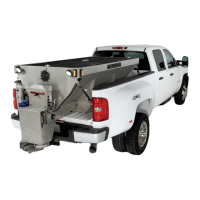
Because of the wide range of possible installations of
this hopper spreader, no pump is supplied with the
unit. If your truck does not have a pump suitable to
your application, one may be purchased from a local
truck equipment supplier. This pump should produce
9 GPM at 1,500 PSI at normal operating speed and
have 1" NPT suction and discharge ports.
Hydraulic Reservoir Installation
Position the reservoir outlet as high, or higher than, the
pump inlet. Keep the hose distance as short as
possible. (Reservoir used should have a capacity of
1-1/2 to 2 times the pump maximum flow rate in gpm.)
Cab Control Valve Installation
1. With the seat fully forward, select a suitable
location to mount the cab control valve allowing for
the operator to adjust the control and to turn it ON
and OFF.
2. Check for clearance with ALL controls in the cab.
3. Under the cab, check for interference with
transmission, etc.
4. Check to see that the cab control valve location
does not interfere with entering or leaving cab.
5. Fabricate a bracket to mount cab control valve in
selected location.
6. Insert a grommet into all holes drilled for this
installation.
7. Mount valve and plumb pump and motor to valve.
For single hydraulic motor and valve option:
Plumb Port “T” to reservoir, Port “P” to pressure
side of pump, and Port “REG” of the valve to Port
“B” of the gearbox motor.
For dual hydraulic motor and valve option:
Plumb Port “Auger” to Port “B” of gearbox motor
and Port “Spinner” to Port “B” of spinner motor.
8. Check machine for proper rotation of drive shafts
and hydraulic leaks.
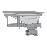
Hydraulic Motor Plumbing
HYDRAULIC UNIT INSTALLATION INSTRUCTIONS
Port A
Port B
FLOW
DIRECTION
 Loading...