Instruction Manual
D101554X012
Vee-Ball Valves
June 2017
3
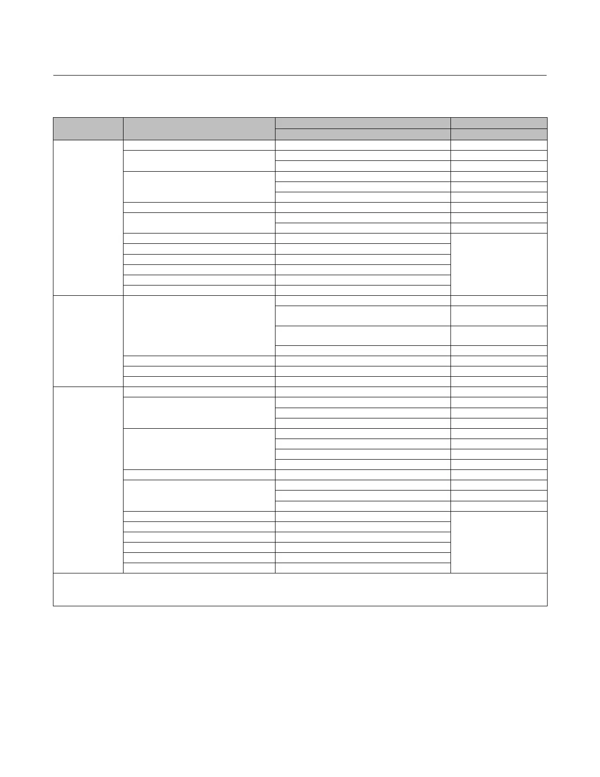
Table 2. Valve Body Materials, End Connections, and Ratings
VALVE DESIGN VALVE BODY MATERIAL
SIZE RATINGS
NPS / DN ASME / PN
V150
WCC NPS 1, 1-1/2, 2, 3, 4, 6, 8, 10, 12, 14, 16, 20, 24x20
(5)
CL150
WCC / 1.0619
(1)
DN 80, 100, 150 PN 10-16
DN 200, 250, 300 PN 10 or PN 16
LCC
NPS 1, 1-1/2, 2, 3, 4, 6, 8, 10, 12 CL150
DN 80, 100, 150 PN 10-16
DN 200, 250, 300 PN 10 or PN 16
CF3M
(2)
NPS 1, 1-1/2, 2, 3, 4, 6, 8, 10, 12 CL150
CF3M/1.4409
(1)
DN 80, 100, 150 PN 10-16
DN 200, 250, 300 PN 10 or PN 16
CG8M NPS 1, 1-1/2, 2, 3, 4, 6, 8, 10, 12, 14, 16, 20, 24x20
(5)
CL150
CW2M NPS 1, 1-1/2, 2, 3, 4, 6, 8, 10, 12
M35-2 NPS 1, 1-1/2, 2, 3, 4, 6, 8
CD3MN
(3)
NPS 1, 1-1/2, 2, 3, 4, 6, 8, 10, 12
CD3MWCuN
(3)
NPS 1, 1-1/2, 2, 3, 4, 6, 8, 10, 12
CK3MCuN NPS 1, 1-1/2, 2, 3, 4, 6, 8, 10, 12
V200
(4)
WCC, LCC, CG8M, or CF3M
(2)
NPS 1, 1-1/2, 2 CL150/300/600 flangeless
NPS 3, 4
CL150 and CL300/600
flangeless
NPS 6, 8
CL150/300 and CL600
flangeless
NPS 10 CL150 flangeless
WCC, LCC, or CG8M NPS 2, 3, 4, 6, or 8 CL600
CW2M, M35-2, or CK3MCuN NPS 1, 1-1/2, 2, 3, 4, 6, 8 CL150/300/600 flangeless
CK3MCuN NPS 10 CL150 flangeless
V300
WCC NPS 1, 1-1/2, 2, 3, 4, 6, 8, 10, 12, 14, 16, 20 CL300
WCC / 1.0619
(1)
DN 25, 40, 50 PN 10-40
DN 80, 100, 150 PN 25-40
DN 200, 250, 300 PN 25 or PN 40
LCC
NPS 1, 1-1/2, 2, 3, 4, 6, 8, 10, 12 CL300
DN 25, 40, 50 PN 10-40
DN 80, 100, 150 PN 25-40
DN 200, 250, 300 PN 25 or PN 40
CF3M
(2)
NPS 1, 1-1/2, 2, 3, 4, 6, 8, 10, 12 CL300
CF3M/1.4409
(1)
DN 25, 40, 50 PN 10-40
DN 80, 100, 150 PN 25-40
DN 200, 250, 300 PN 25 or PN 40
CG8M NPS 1, 1-1/2, 2, 3, 4, 6, 8, 10, 12, 14, 16, 20
CL300
CW2M NPS 1, 1-1/2, 2, 3, 4, 6, 8
M35-2 NPS 1, 1-1/2, 2, 3, 4, 6, 8
CD3MN
(3)
NPS 1, 1-1/2, 2, 3, 4, 6, 8, 10, 12
CD3MWCuN
(3)
NPS 1, 1-1/2, 2, 3, 4, 6, 8, 10, 12
CK3MCuN NPS 1, 1-1/2, 2, 3, 4, 6, 8, 10, 12
1. WCC and EN Stl 1.0619 are dual certified. CF3M and EN SST 1.4409 are dual certified.
2. CF3M is a standard offering in Europe and Asia Pacific.
3. NORSOK compliant materials available upon request.
4. Flangeless V200 assemblies mate with raised-face flanges.
5. Valve body mates with NPS 24 ASME CL150 flanges. Internal based on NPS 20 valve design.
Installation
Separate installation steps are provided in this section for V150 and V300 flanged valves, and for V200 flangeless
valves. Key numbers in installation procedures are shown in figures 24, 25 and 26 unless otherwise indicated.
Some types of ceramic trim, including VTC, can create a spark under certain conditions. If an edge of a ceramic part is
struck against a second ceramic part with enough force, it can produce a spark.

 Loading...


