Instruction Manual
D101554X012
Vee-Ball Valves
June 2017
4
WARNING
Avoid personal injury and property damage from ignition of process fluid caused by sparks from ceramic trim. Do not use
ceramic trim where the process fluid is unstable or if it is an explosive mixture (such as ether and air).
WARNING
Always wear protective gloves, clothing, and eyewear when performing any installation operations to avoid personal
injury.
Personal injury or equipment damage caused by sudden release of pressure may result if the valve assembly is installed
where service conditions could exceed either the valve body rating or the mating pipe flange joint rating. To avoid such
injury or damage, provide a relief valve for overpressure protection as required by government or accepted industry codes
and good engineering practices.
Check with your process or safety engineer for any additional measures that must be taken to protect against process
media.
If installing into an existing application, also refer to the WARNING at the beginning of the Maintenance section in this
instruction manual.
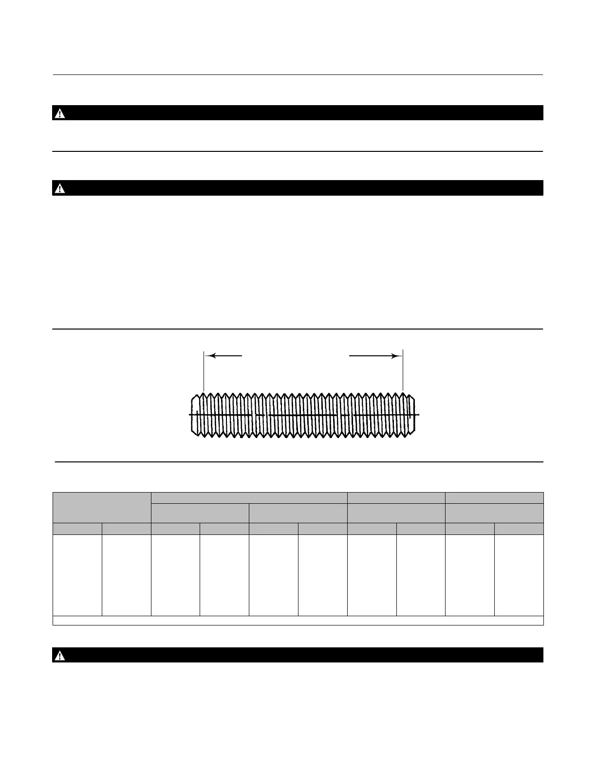
Figure 2. Flange Stud Length for Seal Protector End
DIMENSION SHOWN IN TABLE 3
1A4520
FIRST FULL THREAD TO
FIRST FULL THREAD
Table 3. Flange Stud Lengths Required for Seal Protector Ring End of Fisher V150 and V300 Valves
VALVE
SIZE
V150 V200
(1)
V300
ANSI/ISA S75.08.02
Face‐to‐Face
ASME B16.10 Short
Face‐to‐Face
ANSI/ISA S75.08.02
Face‐to‐Face
ANSI/ISA S75.08.02
Face‐to‐Face
DN NPS mm Inches mm Inches mm Inches mm Inches
25
40
50
80
100
150
200
250
300
1
1-1/2
2
3
4
6
8
10
12
70
83
95
95
108
114
121
133
140
2.75
3.25
3.75
3.75
4.25
4.50
4.75
5.25
5.50
95
127
146
133
146
152
171
165
159
3.75
5.00
5.75
5.25
5.75
6.00
6.75
6.50
6.25
- - -
- - -
121
140
165
197
216
- - -
- - -
- - -
- - -
4.75
5.50
6.50
7.75
8.50
- - -
- - -
89
102
95
121
127
140
152
171
184
3.50
4.00
3.75
4.75
5.00
5.50
6.00
6.75
7.25
1. For the flanged V200, the same bolt lengths are used for both the inlet and outlet flange ends.
WARNING
When ordered, the valve configuration and construction materials were selected to meet particular pressure, temperature,
pressure drop, and controlled fluid conditions. Responsibility for the safety of process media and compatibility of valve
materials with process media rests solely with the purchaser and end‐user. To avoid possible personal injury and because

 Loading...


