Instruction Manual
D101554X012
Vee-Ball Valves
June 2017
7
2. Install two studs in the flanges before you place the valve in the line. Place the two studs so they will contact the
line‐centering notches at the bottom of the valve body.
3. Insert flat‐sheet line flange gaskets (or spiral‐wound gaskets with compression‐controlling center rings) that are
compatible with the process fluid.
4. Place the valve on the two studs. Install all remaining studs. Measure carefully to be sure the valve is centered on the
pipeline flanges, and tighten the flange stud nuts. Tighten the nuts in a criss‐cross sequence to be sure the flange
gaskets are properly torqued.
5. Connect pressure lines to the actuator as indicated in the actuator instruction manual. When an auxiliary manual
actuator is used with a power actuator, install a bypass valve on the power actuator (if one is not supplied) for use
during manual operation.
WARNING
Personal injury could result from packing leakage. Valve packing was tightened before shipment; however the packing
might require some readjustment to meet specific service conditions. Check with your process or safety engineer for any
additional measures that must be taken to protect against process media.
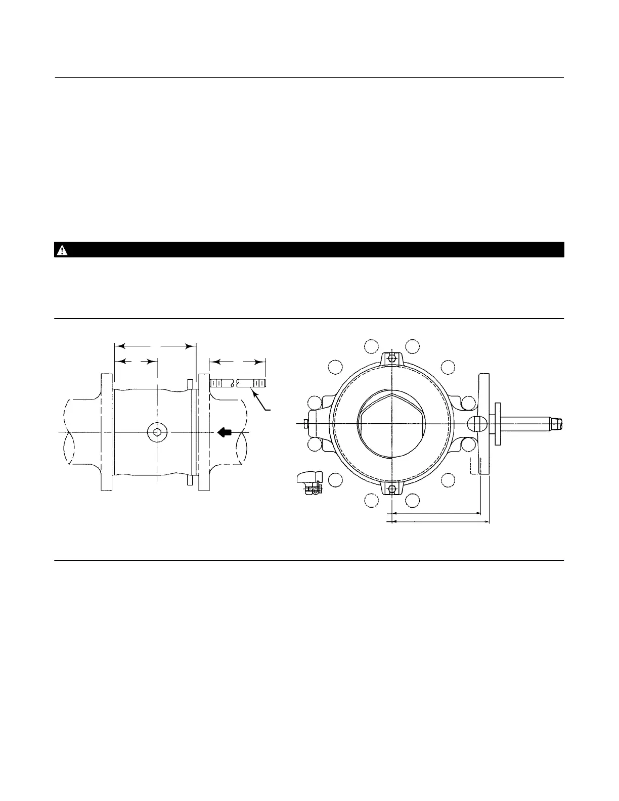
Figure 4. Fisher V200 Dimensions and Required Clearances for Installation
179 mm (7.06 INCHES) FOR CL600 NPS 6 VALVES
164 mm (6.44 INCHES) FOR CL150 AND 300 NPS 6 VALVES
95BA02100B
A6956
A
B
M
KEY
32
12B3060‐L

 Loading...


