Instruction Manual
D101554X012
Vee-Ball Valves
June 2017
6
Installing V150, V300, and Flanged V200 Valves
1. Install the V150 and V300 valve using studs (keys 32 and 33, not shown) and nuts to connect the valve flanges to
the pipeline flanges. The seal protector ring (key 3) end of the valve requires longer line flange studs (key 32) than
standard. Do not use standard‐length line flange studs for the seal protector ring end of the valve. The seal
protector ring end of the valve for the DN25/NPS 1 constructions will have threaded flange holes due to insufficient
nut clearance.
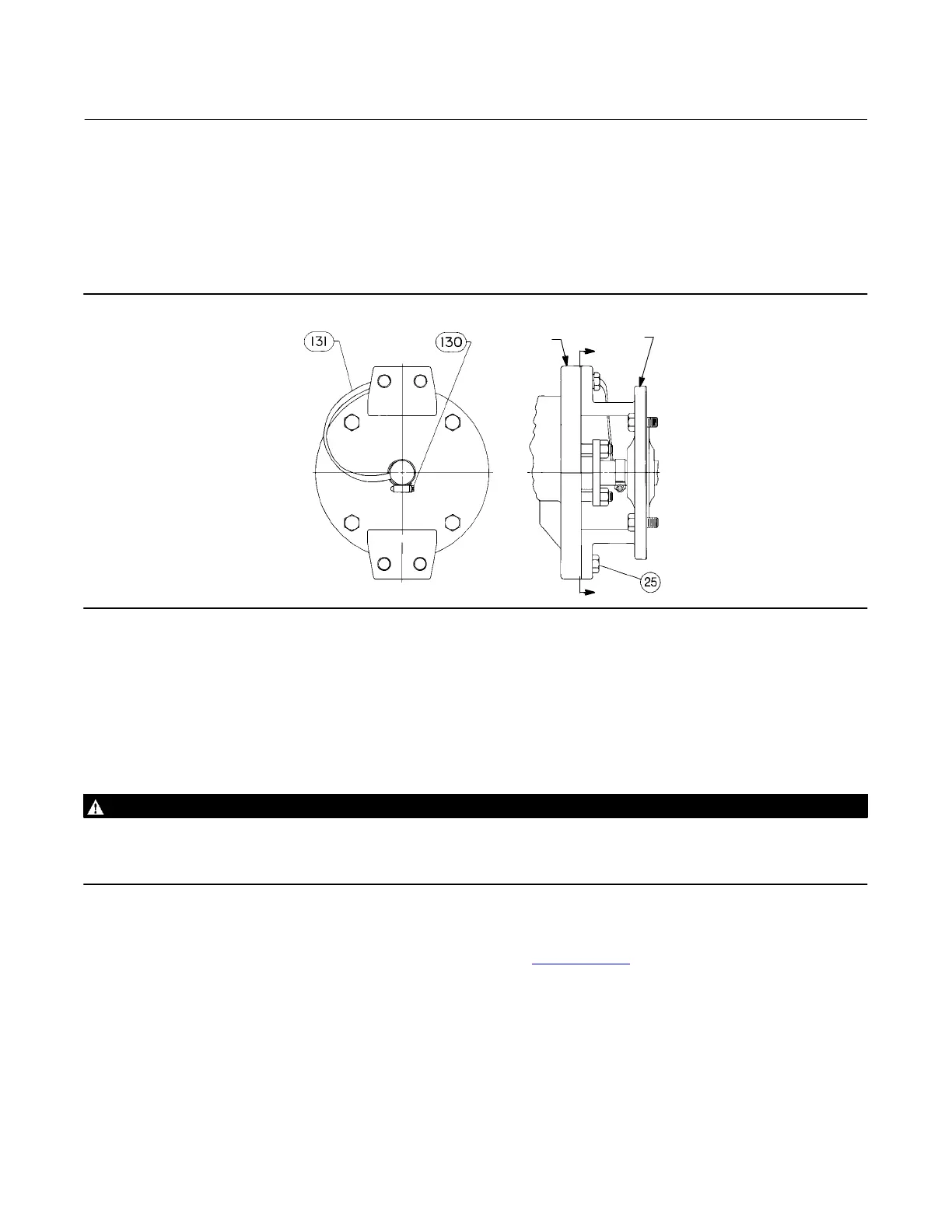
Figure 3. Optional Shaft‐to‐Body Bonding Strap Assembly
VALVE
BODY
ACTUATOR
A
A
VIEW A‐A
37A6528‐A
A3143‐2
2. See table 3 and figure 2 for length of studs for the seal protector ring end of V150 and V300 valves. Lubricate the
studs with anti‐seize lubricant.
3. Insert flat‐sheet line flange gaskets (or spiral‐wound gaskets with compression‐controlling center rings) that are
compatible with the flowing media.
4. Connect pressure lines to the actuator as indicated in the actuator instruction manual. When an auxiliary manual
actuator is used with a power actuator, install a bypass valve on the power actuator (if one is not supplied) for use
during manual operation.
WARNING
Personal injury could result from packing leakage. Valve packing was tightened before shipment; however the packing
might require some readjustment to meet specific service conditions. Check with your process or safety engineer for any
additional measures that must be taken to protect against process media.
If the valve has ENVIRO‐SEAL live‐loaded packing installed, this initial re‐adjustment will probably not be required. See
ENVIRO‐SEAL Packing System for Rotary Valves instruction manual (D101643X012
) for packing instructions.
Installing V200 Valves
Stud length dimensions are shown in figure 4 for the seal protector ring end of the valve. For V200, CL600, the
dimension from the center line of the valve bore to the mounting flange face is larger than a CL150 or 300 valve.
1. Install the V200 valve using long studs (key 32, figure 4) to connect the two pipeline flanges. Refer to figure 4 for
the size of studs required. Lubricate the studs with anti‐seize lubricant.

 Loading...


