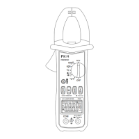
14. Resistance Test
15. Diode Test
Warning
The risk of electric shock.
When measuring the impedance on the circuit, make sure that the power
supply of the circuit is disconnected and the capacitor on the circuit is
completely discharged.
Insert the black test leads into the COM terminal and the red test leads into the INPUT
terminal.
Set the rotary switch to the position, and the meter is in resistance measurement
state at this time.
Connect the test leads to both ends of the measured resistance or circuit for measure-
ment.
Read the measurement data on the LCD display.
When the input is in open circuit, the LCD will display “0L” over-range status.
If the resistance value of the measured resistance is higher than 1MΩ, it may take
several seconds for the meter to stabilize the reading. This is normal for high resistance
readings.
The meter shows the approximate value of the forward voltage drop of the diode.
If the test leads are reversely connected or the test leads are in open circuit, the LCD
will display“0L”.
Insert the black test leads into the COM terminal and the red test leads into the INPUT
terminal.
Set the rotary switch to the position.
Press the “SEL” key to switch to the test status.
Connect the red test leads to the anode of the diode and the black test leads to the
cathode of the diode for testing.
Read the measurement data on the LCD display.
Notice:
Notice:

 Loading...