PowerFLARM Manual Version 1.0
Connections
Overview
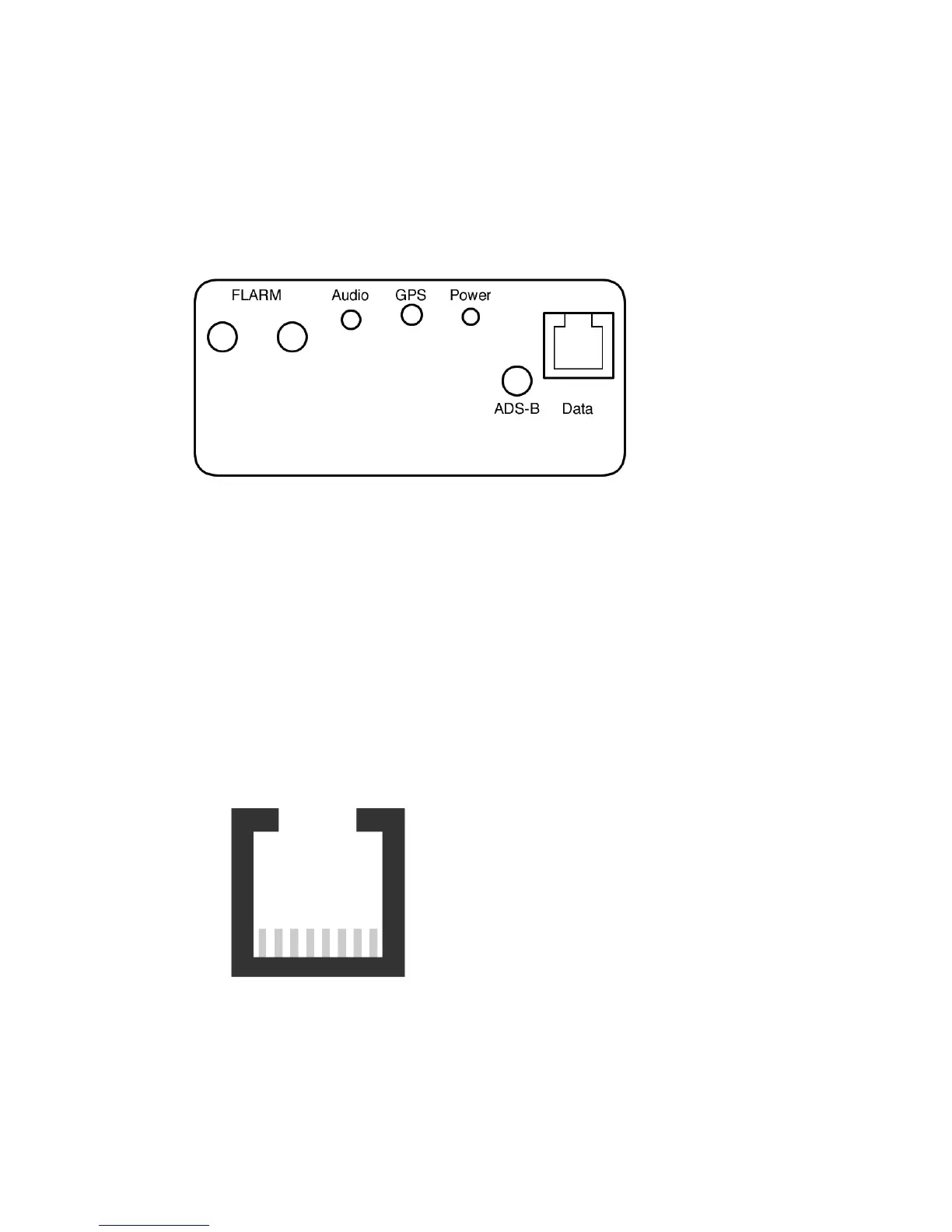
Power and Data Connections
The 8-pin RJ45-socket accepts and retains an 8-pin (temporarily
also a 6-pin) plug. The pin connection is mostly in accordance
with IGC GNSS FR specifications.
(http://www.fai.org/gliding/system/files/tech_spec_gnss.pdf).
An 8-pin (temporarily also a 6-pin) ribbon cable with an RJ45
push-fit connector or an 8-pin twisted-pair patch cable with RJ45
may be used. Suitable cables are obtainable from retailers.
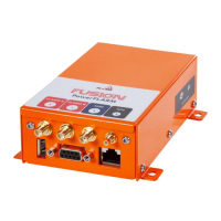
1: +8 to +27V DC
2: +8 to +27V DC
3: PowerFLARM supplies + 3V DC
4: GND
5: TX (RS232): only 1 user!
6: RX (RS232): only 1 user!
7: GND
8: GND
Pin 1 Pin 8 (view from rear)
For 8-pin cables Pins 1=2 are to be linked. Also Pins 7=8. If the
other wires are not to be used, they should be individually
insulated and may not be soldered together or twisted in pairs.