11
ARPEX 8704 en
Operating instructions 01/2019
5. Technical description
5.1 General description
15432
687
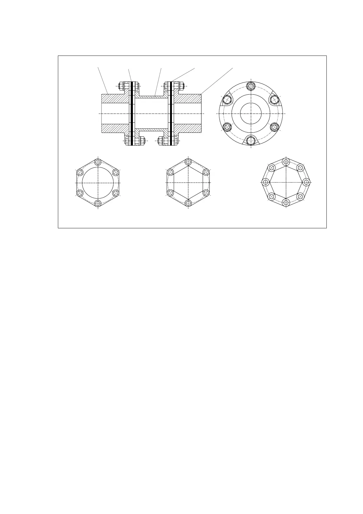
Fig. 3: Hexagonal plate pack and octagonal plate pack
1 Hub
2 Plate pack
3 Spacer
4 Plate pack
5 Hub
6 Hexagonal ring plate pack
7 Hexagonal tie plate pack
8 Octagonal tie plate pack
ARPEX couplings are allsteel couplings. The plate packs are arranged between the flanges of the
coupling parts and bolted to them alternately.
The individual plates are threaded onto bushes and clamped together with a clipped on, internally bevelled
retaining rings. The retaining rings are held on by the expanded bush ends, which lie against the angled
face.
So constructed, the plate pack in ring plate pack designs forms a complete unit. In tie plate packs the
individual tie plates are crimped together to form plate strands and then pushed together in the shape of
a ring to form the plate pack.
Through this arrangement of the plate packs the ARPEX coupling is torsionresistant and transmits the
torque without circumferential backlash. In axial and radial direction the coupling is however still flexible
and can absorb axial, radial and angular misalignment of the coupled units.
Depending on the series, collar bolts and nuts or conical screw connections join the plate packs to sleeve
and coupling part flanges.
The size designation of the coupling indicates the outside flange diameter (d
a
) of the coupling in mm and
the configuration of the plate pack ("6" = hexagonal) This information is prefixed by a letter combination
specifying the component parts of the coupling.
Example: ARS6 NHN 2556
Coupling with 2 hubs (N) and 1 "H" spacer (H) size 2556 with hexagonal plate pack in
the ARS6 series