15
ARPEX 8704 en
Operating instructions 01/2019
6.2.1.1 Parallel keyway
The parallel keyways must be designed to suit the available parallel keys. For parallel keyways the
tolerance zone of the hub keyway width ISO P9 must be adhered to.
6.2.2 Axial fastening
A set screw or end plate must be provided to secure the coupling parts axially. If end plates are used,
Flender must be consulted with regard to machining the recesses in the coupling parts.
6.2.3 Set screws
To prevent damage to the shafts, the setscrew hole should be arranged on the parallel
keyway.
In exceptional cases the set screw must be offset 180° to the parallel keyway, if
because of the diameter of the drilled hole and hub core too little material is left
between the parallel keyway and the hub core (e.g. series ARS6, size 786).
e
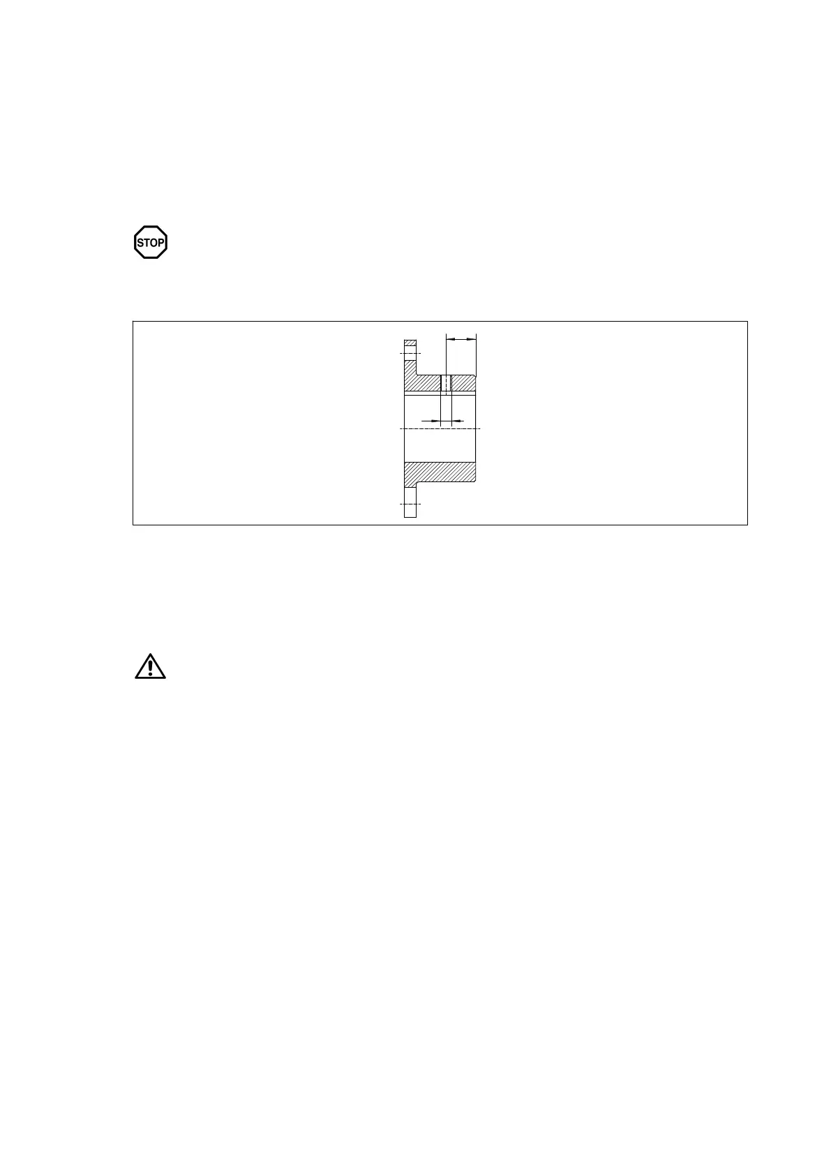
M
Fig. 5: Setscrew bore
The following guidelines must be observed:
The set screw should be inserted in the centre of the hub core (see figure 5). If this option is not possible,
care must be taken that the distance (e) is at least M x 1.5.
Use a threaded stud with cup point to DIN 916 for set screws.
The length of the set screw must be selected so that it fills the threaded hole, but does
not project from the hub (L
min.
= M x 1.2).