27
ARPEX 8704 en
Operating instructions 01/2019
1
2
3
1)
4
5
67
1)
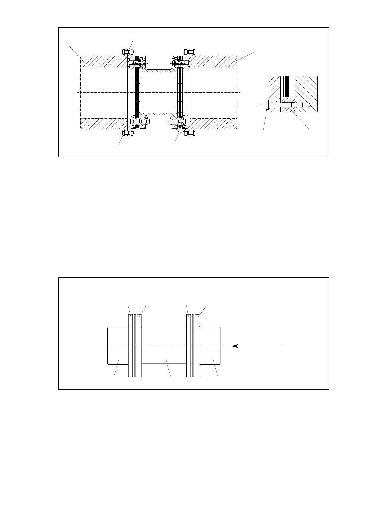
Fig. 19: Fflange connection (example ARC)
1)
Detail "X"
1"F" flange
2 Connection provided by the customer
3 Close-fitting bolt with collar nut
4 Connection provided by the customer
5 Transport lock / mounting aid
6 Tensioning bolt
7 Fitting spacer
6.10 Fitting of assemblybalanced couplings
On couplings which have been assemblybalanced each individual coupling component must be marked
on the outside diameter of the flange with a fourdigit number (Figure 20, "AAAA"). When assembling, care
must be taken that only coupling parts having the same numbers on the outside circumference of the flange
are bolted together. The coupling parts must be arranged so that the numbers are in line and can be read
from one direction (see figure 20). Only in this way will the balancing condition meet the requirements!
1
234
AAAA
AAAA
AAAA
AAAA
Fig. 20: Marking in case of assembly balancing
1 readable from here
2 Hub 1
3 Spacer
4 Hub 2