14
ARPEX 8704 en
Operating instructions 01/2019
6.2 Instructions for machining the finished bore, axial fastening, set screws and balancing
6.2.1 Finished bore
Remove preservative agent from coupling parts.
Observe the manufacturer’s instructions for handling the solvent.
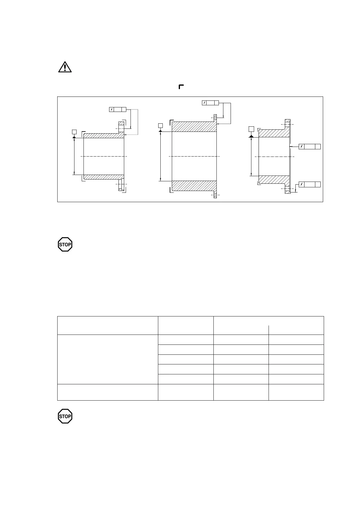
When machining the finished bore the parts must be carefully aligned.
The parts must be fitted on the marked faces (
) (see figure 4).
1
2
Ø D1
Ø D1
Ø D1
3
AIT 7
A
BIT 7
B
CIT 7
C
CIT 7
Fig. 4: Finished bore to ISO tolerances
1"N"-hub / "B"-hub
2"M"-hub
3"M"-hub
The maximum permissible bore diameters (see section 1, "Technical Data") are
designed for drivetype fastenings without taper action to DIN 6885/1 and must not
under any circumstances be exceeded. The finishmachined bores must be 100 %
checked with suitable measuring equipment.
If other shafthub connections (such as splined hub profiles, taper or stepped bores and drivetype
fastenings with taper action or other connections) are to be used instead of the drivetype fastenings
provided for, Flender must be consulted.
For drive by means of parallel keys the following fit pairs are prescribed for the bores (see table 3):
Table 3: Fit pairs
Type of fit Shaft tolerance
Bore tolerances
Reversing operation Setting-up operation
Interference fit with parallel-key
connection
h6 P7 N7
k6 M7 H7
m6 K7 H7
n6 J7 H7
p6 H7 F7
Shrink fit without parallel-key connection
to customer
specification
on request on request
The assigned fits must be adhered to in order, on the one hand, to keep the play in the
shafthub connection as low as possible, depending on utilisation of the tolerance
zones, and, on the other, to keep the hub tension arising from the oversize within the
permissible load limit. Failure to adhere to the assigned fits may impair the shafthub
connection.