13
If you are using a digital receiver connecon, and have completed the steps on page 12, skip ahead to the next page.
PWM is an acronym that stands for Pulse Width Modulaon. PWM is how tradional receivers send a signal to the servo to command the servo
move to a parcular posion. In short, PWM in regards to the Cessna requires the use of male to male servo extensions to connect each channel
from your receiver, to each port in the Aura. Due to the aps and the ight modes in the Aura, a minimum of a 6-channel receiver and transmier is
required to maximize the funconality of the Cessna 170. A 7+ channel receiver and transmier is recommended.
Depending on your parcular radio and PWM setup, some addional items to purchase are required:
1.
2.
3.
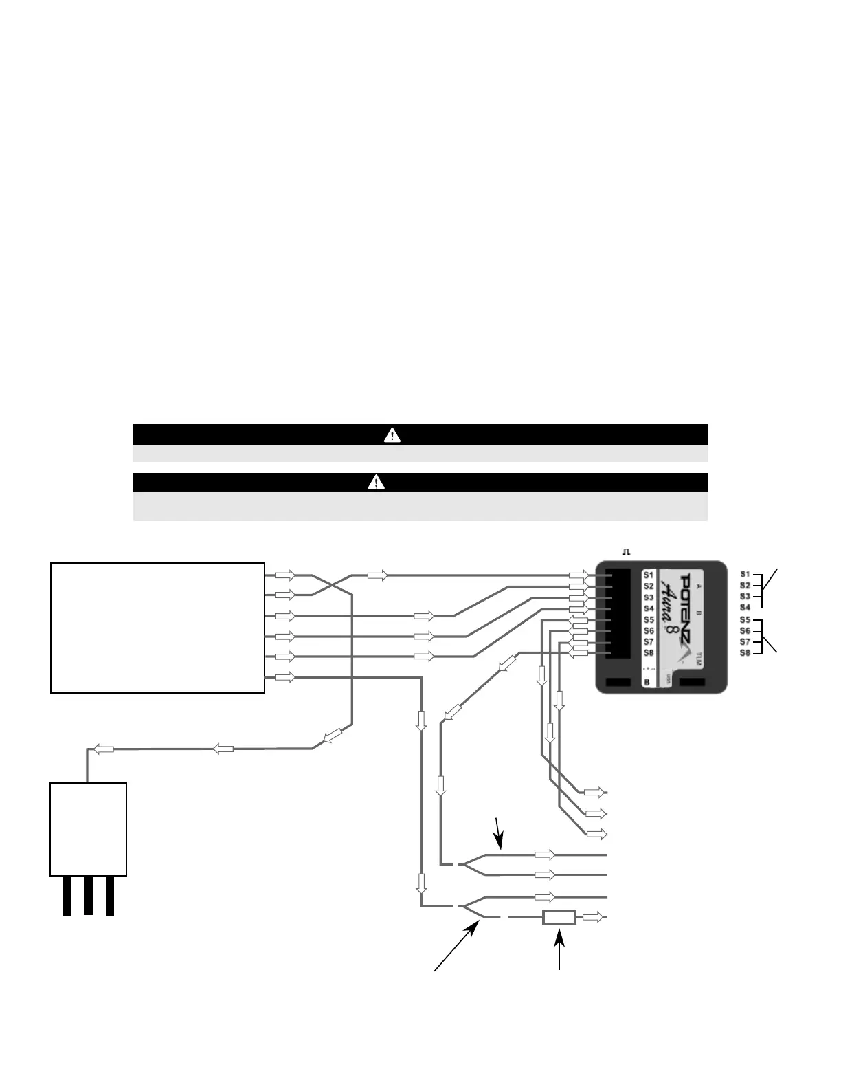
RECEIVER INSTALLATION/SERVO CONNECTIONS (CONTINUED)
PWM Connecons
RECEIVER
Throle
Aileron
Elevator
Rudder
Gear/Ch.5
Aux 1/Ch.6
ESC
To Motor
To RX
Le Aileron Servo
Right Aileron Servo
Elevator Servo
Rudder Servo
Float Rudder Servo
Le Flap Servo
Right Flap Servo
Y-Harness*
(FPZA1012)
Servo Reverser*
(FPZA1011)
FPZAU01
FPZA1011
FPZA1012
Aura 3 piece male to male servo cable/S.Bus
*In-Line Servo Reverser (one for aps)
*2-inch Y-Harness (one for aps, two if using oats)
*Note: Y-Harness and Servo Reverser not required if using a 7+ channel receiver/transmier with dual ap servo and independent reversing capability
**Note: Arrows indicate signal (data) ow. They do not necessarily indicate voltage (+) ow.
- +
Aura Polarity
NOTICE
VERIFY PROPER POLARITY OF ALL CABLE CONNECTIONS PRIOR TO ADDING POWER TO THE SYSTEM
IMPORTANT
All four PWM male-to-male connecons must be connected AND connected in the proper polarity for the
Aura to acvate servo outputs. (Aileron-S1, Elevator-S2, Rudder-S3, Gear/Ch.5-S4)
Y-Harness*
(FPZA1012)
Aura Data Input Aura Data Output
**
Bind your receiver to your transmier by following the instrucons included with your radio and/or receiver. Verify it is bound by connecng a
spare servo to your receiver, and that it responds to transmier inputs.
With the transmier and receiver powered OFF, connect your receiver to the Aura using the diagram below. Note the throle AND both aps are
plugged directly into the receiver. Important: all four (4) PWM male-to-male leads must be properly connected for the Aura to acvate servo
outputs!
With the propeller removed and ALL connecons made between the Aura and the receiver (and in the proper polarity), power on your
transmier, and power on the airplane with the ight baery, and keep the airplane staonary. Aer a few seconds, the LEDs on the Aura will
sweep back and forth as the Aura searches for a valid control signal. Once found, you will see a solid orange (Aura running) and solid green (Aura
is receiving a valid signal from the receiver) LED. Aer the source is found, apply transmier right rudder to assist Aura in determining your
radio type, then you will have control of the model.