RUDDER INSTALLATION
Required Tools and Fasteners: Medium CA
2mm Hex Driver
4
1.
2.
3.
4.
5.
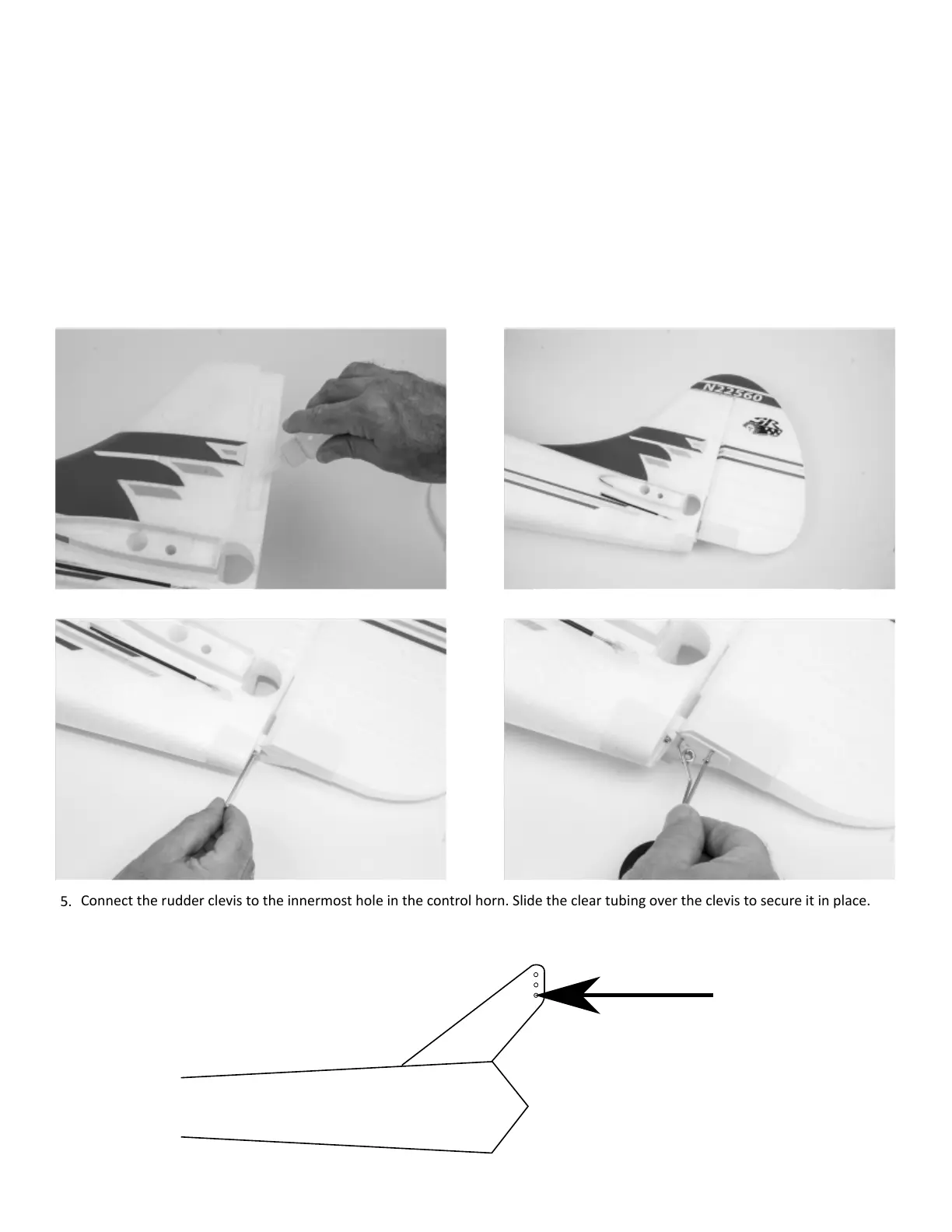
Connect the rudder clevis to the innermost hole in the control horn. Slide the clear tubing over the clevis to secure it in place.
Aer assembly is complete, and your receiver is bound and transmier properly set up, center the rudder by turning the clevis
in or out as needed. Use the rudder counter balance and xed poron of the vercal n for reference. Do NOT use trim or sub-
trim.
The rudder comes pre-hinged to a small secon of vercal n. Test t the rudder and n secon onto the fuselage. Remove it from the
fuselage once t is conrmed.
Lay the fuselage on its side, and using medium CA (foam-safe is not required), apply an adequate amount to the fuselage. Press the rudder and
vercal n secon into the fuselage, being sure to wipe away any excess CA.
Secure the lower plasc support in place by threading an M3x10 hex head self-tapping screw through the boom of the plasc part in the
fuselage. Do not fully ghten, as you can cause the rudder to bind. A small amount of play is needed here.
Allow me for the CA to dry, and once dry, check for proper rudder movement. Be sure the rudder moves freely with lile to no binding.
Press the tailwheel wire into the plate on the boom of the rudder. Lay the tailwheel plate over the wire, and secure it in place with two
M3x10 hex head self-tapping screws.
5.
3 - M3x10 Hex Head Self-Tapping Screw