FLUXUS F70x 7 Connection
56 UMFLUXUS_F7V4-6-2EN, 2017-10-01
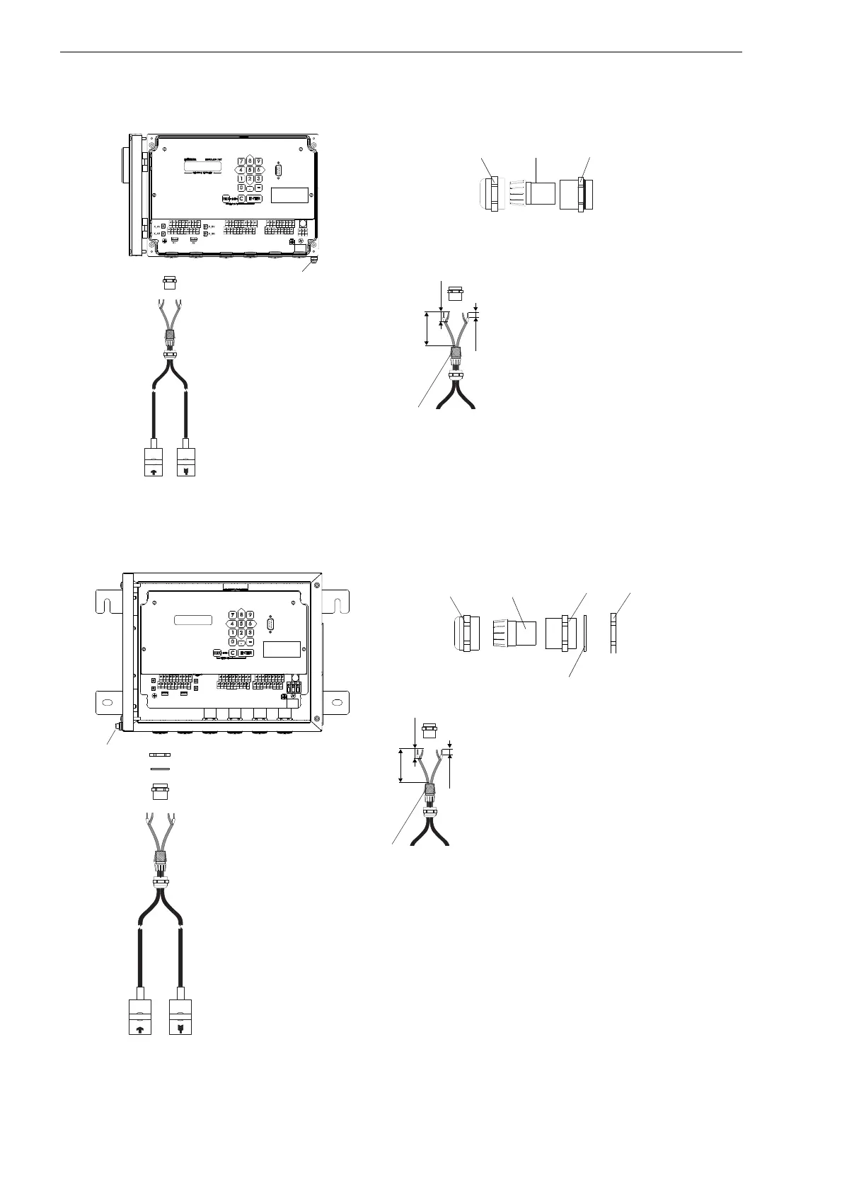
Fig. 7.7: Connection of the transducer cable
with plastic cable jacket and stripped cable ends
to the transmitter FLUXUS F704
Fig. 7.8: Connection of the transducer cable with plastic cable jacket and stripped cable ends
to the transmitter FLUXUS F705, F706 (example with FLUXUS F705)
AVSAV
AGN
ARS
AR
BVSBV
BGN
BRS
BR
SA1
SA2
SA3
SA4
SB1
SB2
SB3
SB4
T1a
T1b
S2 T2a
T3a
T3b
S4
T4a
T2b
T4b
T1A
T1B
S1 T2A
T3A
T3B
S3
T4A
T2B
T4B
A+
B-
P1+ P2+
P4+
P5a
P6a P7a
P3+
101
103
P1- P2-
P4-
P5b
P6b
P7b
P3-
PE
N(-)
L(+)
U L T R A S O N I C F L O W M E T E R
1 32
0
4 65
7 8
N E X T
Q
O N
Q -
Q +
M U X
D I S P
Q
O F F
9
D I S P
E N T E R
C
B R K
R E S T A R T
I N I T
external shield,
brushed back
cap nut
compression part basic part
equipotential bonding terminal
(FLUXUS F704**-A2)
70 mm
10 mm
20 mm
cable gland
U L T R A S O N I C F L O W M E T E R
1 32
0
4 65
7 8
N E X T
Q
O N
Q -
Q +
M U X
D I S P
Q
O F F
9
D I S P
E N T E R
C
B R K
R E S T A R T
I N I T
cap nut compression part basic part
counter nut
sealing ring:
only for cable gland M20,
not for cable gland 1/2 NPS
AVS
AV
AGN
ARS
AR
BVS
BV
BGN
BRS
BR
SA1
SA2
SA3 SA4 SB1
SB2
SB3
SB4
T1a T1b
S2 T2a
T3a
T3b
S4
T4a
T2b
T4b
T1A T1B
S1 T2A
T3A
T3B
S3
T4A
T2B
T4B
A+
B-
P1+ P2+
P4+
P5a
P6a P7a
P3+
101
103
P1- P2-
P4-
P5b
P6b
P7b
P3-
PE
N(-)
L(+)
external shield,
brushed back
70 mm
10 mm
20 mm
cable gland
equipoten-
tial bonding
terminal

 Loading...


