7 Connection FLUXUS F70x
UMFLUXUS_F7V4-6-2EN, 2017-10-01 77
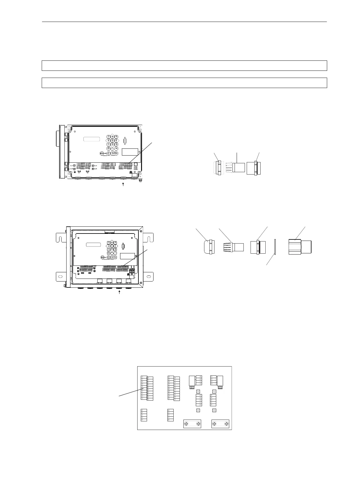
7.4 Outputs
FLUXUS F704, F705, F706
For the connection of the output cable to the transmitter, see box Cable connection S. 75, Fig. 7.1 or Fig. 7.2, Fig. 7.39 or
Fig. 7.40 and Tab. 7.19
.
FLUXUS F709
• Prepare the output cable.
• Connect the output cable to the terminals of the transmitter (see Fig. 7.4, Fig. 7.41 and Tab. 7.19).
Attention! Observe the "Safety Instructions for the Use in Explosive Atmosphere" (see document SIFLUXUS).
Attention! The outputs can only be connected to a low voltage circuit (max. 30 V AC or 42 V DC against earth).
Fig. 7.39: Transmitter FLUXUS F704
Fig. 7.40: Transmitter FLUXUS F705, F706
(example with FLUXUS F705)
Fig. 7.41: Transmitter FLUXUS F709
AVSAV
AGN
ARS
AR
BVSBV
BGN
BRS
BR
SA1
SA2
SA3
SA4
SB1
SB2
SB3
SB4
T1a
T1b
S2 T2a
T3a
T3b
S4
T4a
T2b
T4b
T1A
T1B
S1 T2A
T3A
T3B
S3
T4A
T2B
T4B
A+
B-
P1+ P2+
P4+
P5a
P6a P7a
P3+
101
103
P1- P2-
P4-
P5b
P6b
P7b
P3-
PE
N(-)
L(+)
cable gland
cap nut
compression part basic part
outputs
AVS
AV
AGN
ARS
X2
X_BV
X_BR
X_AV
X_AR
X1
AR
BVS
BV
BGN BRS
BR
SA1 SA2 SA3 SA4 SB1
SB2
SB3
SB4
T1a T1b
S2 T2a
T3a
T3b
S4
T4a
T2b
T4b
T1A T1B
S1 T2A
T3A
T3B
S3
T4A
T2B
T4B
A+
B-
P1+ P2+
P4+
P5a
P6a P7a
P3+
101
103
P1- P2-
P4-
P5b
P6b
P7b
P3-
PE
N(-)
L(+)
cap nut compression part basic part
ferrite nut
cable gland
sealing ring:
only for cable gland M20,
not for cable gland 1/2 NPS
K L 7
K L 5
K L 3
K L 1
X 7
K L 4K L 2
X 6 A V
X 8 B V
X 6 A R X 8 B R
X 5
BA
K L 6
K L 8
C H A N N E L
S A 3
S A 1
S A 2
S A 4
S B 3
S B 1
S B 2
S B 4
A V S
A V
A R S
A G N
A R
B V S
B V
B R S
B G N
B R
4 A +
4 B -
4 2
4 3
4 1
L +
L -
N
L 1
P E
P 6 a
P 7 a
P 7 +
P 5 a
P 6 +
P 2 +
P 5 +
P 1 +
P 3 +
P 4 +
P 6 b
P 7 b
P 7 -
P 5 b
P 6 -
P 2 -
P 5 -
P 1 -
P 3 -
P 4 -
T 4 A
T 4 B
T 3 B
S 3
T 3 A
T 1 B
T 2 B
T 1 A
S 1
T 2 A
T 4 a
T 4 b
T 3 b
S 4
T 3 a
T 1 b
T 2 b
T 1 a
S 2
T 2 a

 Loading...


