FLUXUS F70x 18 Outputs
160 UMFLUXUS_F7V4-6-2EN, 2017-10-01
18.7.4 Alarm Outputs During the Measurement
An alarm output with switching condition MAX or MIN will be updated max. once per second to avoid humming (i.e. fluctua-
tion of the measured values around the value of the switching condition).
An alarm output of the type NON-HOLD will be activated if the switching condition is met. It will be deactivated if the switch-
ing condition is no longer met. The alarm will remain activated min. 1 s even if the switching condition is met for a shorter
period of time.
Alarm outputs with the switching condition QUANT. will be activated if the limit is reached.
Alarm outputs with the switching condition ERROR will only be activated after several unsuccessful measuring attempts.
Therefore, typical short-term disturbances of the measurement (e.g., switching on of a pump) will not activate the alarm.
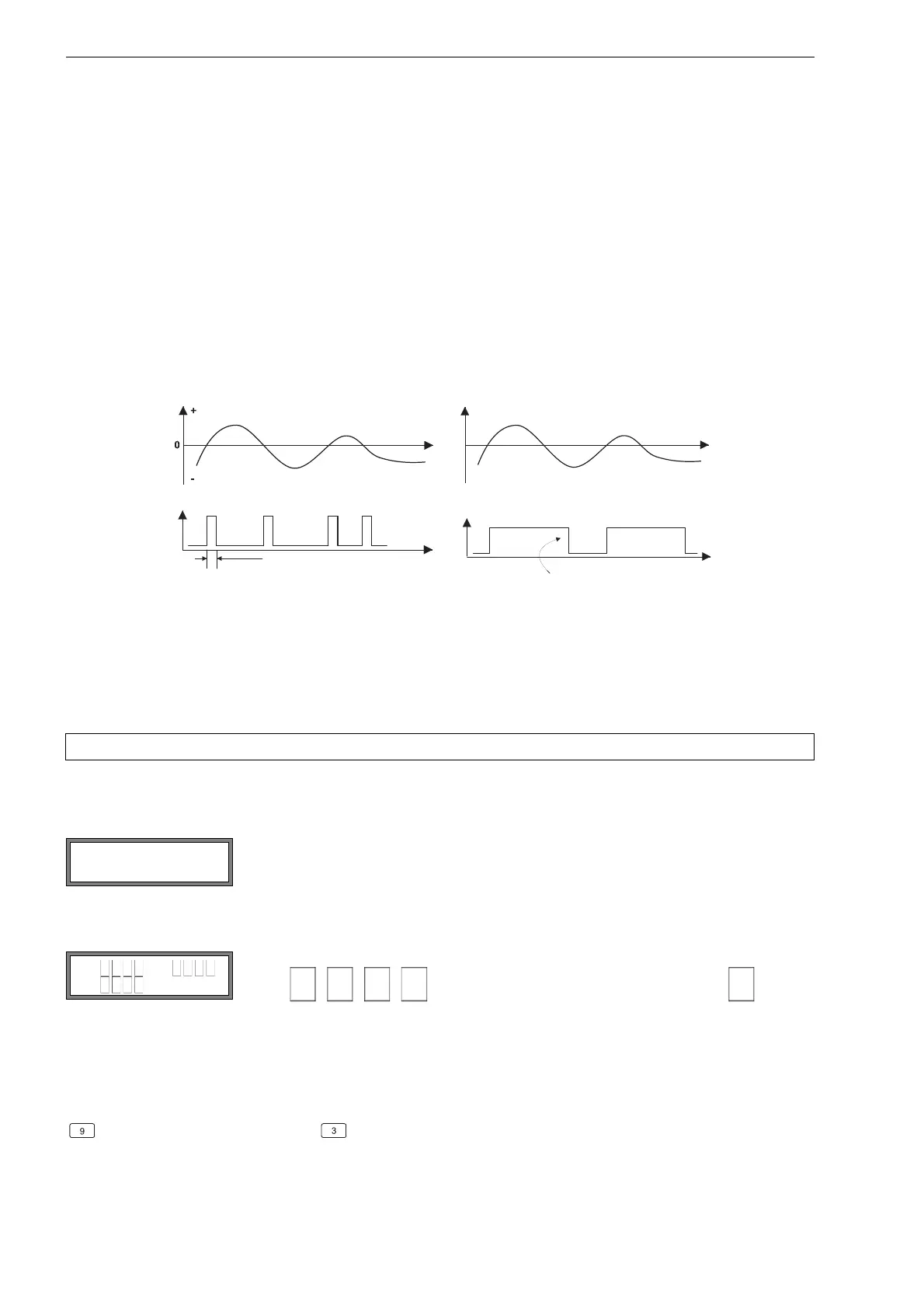
Alarm outputs with the switching condition +→- -→+ and of the type NON-HOLD will be activated with each change of the
flow direction for approx. 1 s (see Fig. 18.2).
Alarm outputs with the switching condition
+→- -→+ and of the type HOLD will be active after the first change of the flow di-
rection. They can be switched back by pressing key C three times (see Fig. 18.2).
If there is an internal adaptation to changing measuring conditions, e.g., to a considerable rise of the medium temperature,
the alarm will not switch. Alarm outputs with the switching condition OFF will be set automatically to the switching function
NO Cont..
18.7.5 Indication of the Alarm State
After the configuration of the alarm outputs and during the measurement, the state of the alarms can be indicated. This
function is activated in the program branch Special Funct.\SYSTEM settings\Dialogs/Menus. It is recommend-
ed to activate this function if the alarm outputs often have to be reconfigured.
If the indication of the alarm state is activated, the state of the alarm outputs will be indicated after the configuration of the
alarm outputs:
Fig. 18.2: Behavior of a relay when the flow direction changes
Note! There is no visual or acoustic indication of alarm output switching.
Select the menu item SHOW RELAIS STAT. Select on to activate the indication of the
alarm state.
The indication of the alarm state is structured as follows:
RX =
, where X is the number of the alarm output and
is a pic-
togram according to Tab. 18.6.
It is possible to repeat the configuration of the alarm outputs by pressing key C. If the con-
figuration of the alarm outputs is complete, press ENTER. The main menu will be dis-
played.
If the indication of the alarm state is activated, it is possible to show the alarm state during the measurement. Press key
to scroll through the upper line and to scroll through the lower line until the alarm state is indicated.
D u r c h f l u s s
+
-
0
A l a r m t y p : H A L T E N D
C
M a n u e l l e s R ü c k s e t z e n
d e s A l a r m s
flow
type NON-HOLD
type HOLD
reset of the alarm
(3x key C)
approx. 1 s
flow
 Loading...


