7 Connection FLUXUS F70x
UMFLUXUS_F7V4-6-2EN, 2017-10-01 57
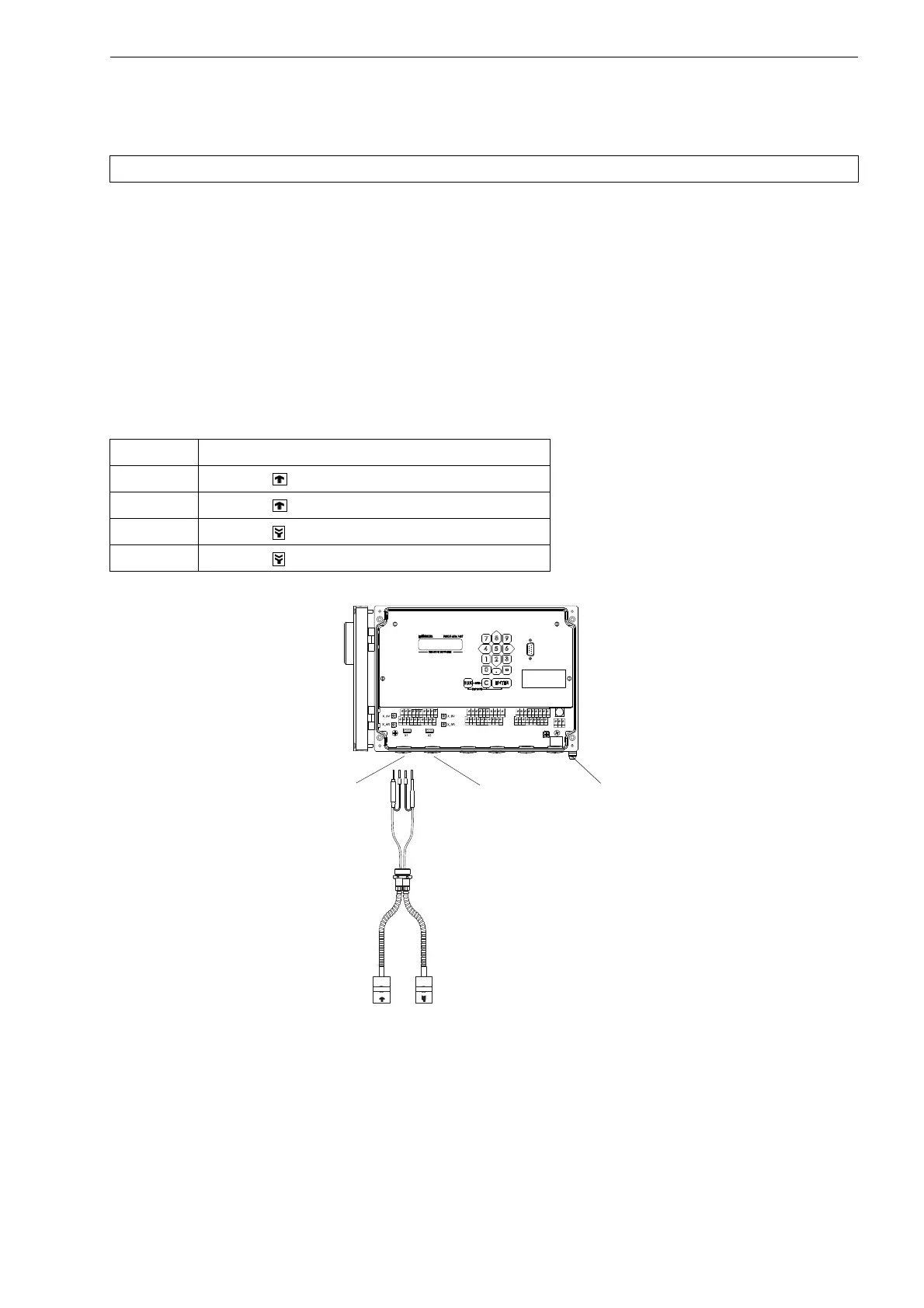
7.1.1.3 Transducer Cable with Stainless Steel Conduit and Stripped Cable Ends
• Remove the left blind plug for the connection of the transducer cable (see Fig. 7.9 or Fig. 7.10).
FLUXUS F704
• Insert the transducer cable into the housing.
• Fix the transducer cable by tightening the cable gland.
• Connect the transducer cable to the terminals of the transmitter (see Fig. 7.1, Fig. 7.9 and Tab. 7.3).
FLUXUS F705, F706
• Push the transducer cable through the sealing ring (only for cable gland M20, not for cable gland 1/2 NPS).
• Insert the transducer cable into the housing.
• Fix the transducer cable by tightening the cable gland with the counter nut.
• Connect the transducer cable to the terminals of the transmitter (see Fig. 7.2, Fig. 7.10 and Tab. 7.3).
Attention! Observe the "Safety Instructions for the Use in Explosive Atmosphere" (see document SIFLUXUS).
Tab. 7.3: Terminal assignment (transducer cable)
terminal connection
AV transducer (white cable, marked white)
AVS transducer (red cable)
ARS transducer (red cable)
AR transducer (white cable)
Fig. 7.9: Connection of the transducer cable with stainless steel conduit
and stripped cable ends to the transmitter FLUXUS F704
AVSAV
AGN
ARS
AR
BVSBV
BGN
BRS
BR
SA1
SA2
SA3
SA4
SB1
SB2
SB3
SB4
T1a
T1b
S2 T2a
T3a
T3b
S4
T4a
T2b
T4b
T1A
T1B
S1 T2A
T3A
T3B
S3
T4A
T2B
T4B
A+
B-
P1+ P2+
P4+
P5a
P6a P7a
P3+
101
103
P1- P2-
P4-
P5b
P6b
P7b
P3-
PE
N(-)
L(+)
transducers
measuring channel B
transducers
measuring channel A
equipotential bonding terminal
(FLUXUS F704**-A2)
 Loading...


