7 Connection FLUXUS F70x
UMFLUXUS_F7V4-6-2EN, 2017-10-01 85
If transducers are replaced or added, the sensor module has to be replaced or added.
FLUXUS F704, FLUXUS F705
• Disconnect the power supply from the transmitter.
• For the connection of the AMP-Quick connector (connection system AS), see section 7.1.2.1.
• For the connection of the separate sensor module (connection system TS):
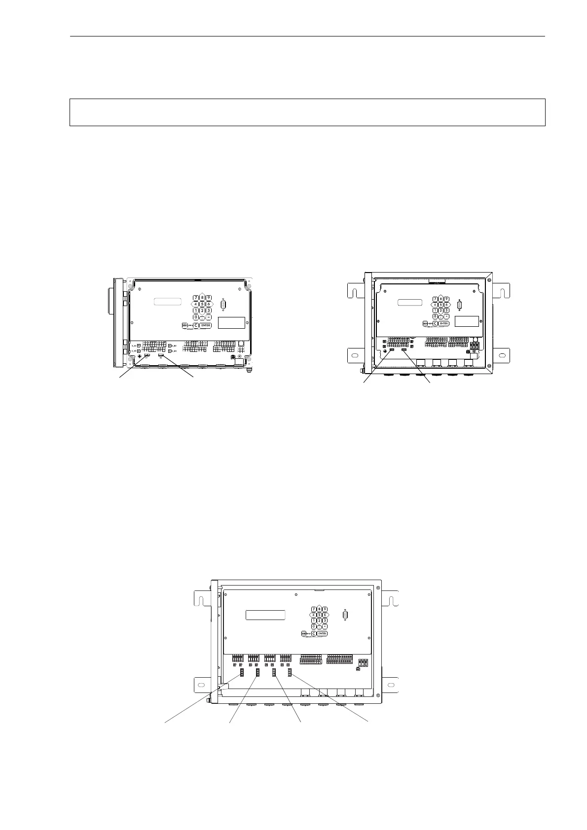
– Insert the sensor module into the lower row of terminal strip (see Fig. 7.1 or Fig. 7.2 and Fig. 7.51 or Fig. 7.52). The slots
SA1...SA4 are assigned to the transducers of measuring channel A, the slots SB1...SB4 are assigned to the transducers
of measuring channel B.
• Connect the transmitter to the power supply.
• Enter all parameters of the program branch Stop Charging.
• Press ENTER until the main menu is displayed again.
FLUXUS F706
• Disconnect the power supply from the transmitter.
• For the connection of the AMP-Quick connector (connection system AS), see section 7.1.2.1.
• For the connection of the separate sensor module (connection system TS):
– Insert the sensor module into the lower row of terminal strip (see Fig. 7.1 or Fig. 7.2 and Fig. 7.51 or Fig. 7.52). The
slots ROM A are assigned to the transducers of measuring channel A, the slots ROM B are assigned to the transduc-
ers of measuring channel B, the slots ROM C are assigned to the transducers of measuring channel C, the slots ROM
D are assigned to the transducers of measuring channel D.
• Connect the transmitter to the power supply.
• Enter all parameters of the program branch Stop Charging.
• Press ENTER until the main menu is displayed again.
Note! The serial number of sensor module and transducer have to be identical. A wrong or incorrectly con-
nected sensor module will lead to incorrect measured values or to a measurement failure.
Fig. 7.51: Transmitter FLUXUS F704 Fig. 7.52: Transmitter FLUXUS F705
Abb. 7.53: Messumformer FLUXUS F706
AVSAV
AGN
ARS
AR
BVSBV
BGN
BRS
BR
SA1
SA2
SA3
SA4
SB1
SB2
SB3
SB4
T1a
T1b
S2 T2a
T3a
T3b
S4
T4a
T2b
T4b
T1A
T1B
S1 T2A
T3A
T3B
S3
T4A
T2B
T4B
A+
B-
P1+ P2+
P4+
P5a
P6a P7a
P3+
101
103
P1- P2-
P4-
P5b
P6b
P7b
P3-
PE
N(-)
L(+)
sensor module
measuring channel A
sensor module
measuring channel B
AVS
AV
AGN
ARS
X2
X_BV
X_BR
X_AV
X_AR
X1
AR
BVS
BV
BGN BRS
BR
SA1 SA2 SA3 SA4 SB1
SB2
SB3
SB4
T1a T1b
S2 T2a
T3a
T3b
S4
T4a
T2b
T4b
T1A T1B
S1 T2A
T3A
T3B
S3
T4A
T2B
T4B
A+
B-
P1+ P2+
P4+
P5a
P6a P7a
P3+
101
103
P1- P2-
P4-
P5b
P6b
P7b
P3-
PE
N(-)
L(+)
sensor module
measuring channel A
sensor module
measuring channel B
T1a
T1b
S2 T2a
T3a T3b S4
T4aT2b
T4b
T1A T1B S1 T2A T3A T3B S3 T4AT2B T4B
A+ B- P1+ P2+ P4+ P5a P6a P7aP3+
101 103 P1- P2- P4- P5b P6b P7b
P8a P9a
P8b P9bP3-
PE
N(-)
L(+)
AVSAV
AGN
ARS
AR
BVSBV BGN BRS
BR
CVSCV CGN CRS
CR
DVSDV DGN DRS
DR
X_ARX_AV
KL3 KL2 KL1
ROM A
ROM B
ROM C
ROM D
X_BV X_BR X_CV X_CR X_DV X_DR
sensor module
measuring channel A
sensor module
measuring channel C
sensor module
measuring channel D
sensor module
measuring channel B
 Loading...


