6 Connections
The indicator utilizes industrial standard RJ45 connectors for connecting
to most peripheral equipment. However care must be taken as the pin
outs are not exchangeable and might interfere with external equipment
in case of incorrect/unsupported connections.
See section 2 Installation for location of the connectors.
For a more detailed description, pin-out and connection diagram for the
interfaces consult the 4-55424 Weight indicator 47-11 Instruction
manual
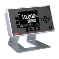
6.1 Load cell / scale connection
The load cell/scale connector is a standard shielded RJ45 plug, located
furthest from the DC-plug.
To ensure proper operation and best signal integrity the scale and
indicator should be grounded to a common point:
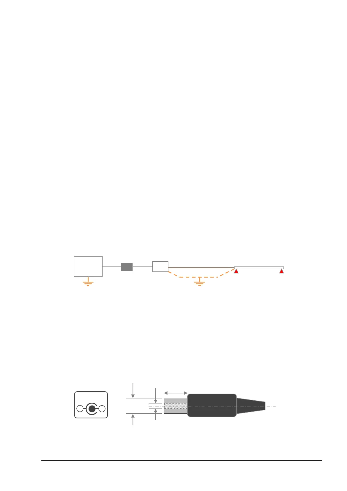
6.2 Power supply
The indicator needs a power source with the specification 10-24VDC
±20% 5W. A suitable power supply is normally supplied with the
indicator.
The power connector is a DC-plug for 2.0mm centre pin with maximum
insertion depth 10mm.
Centre pin is positive.