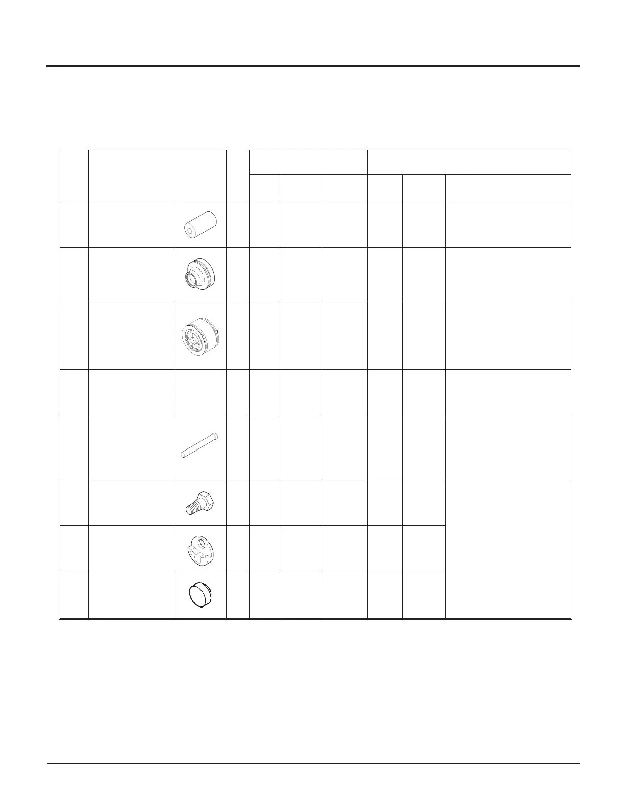
Replacement parts
The view of the intensifier shown on Page 16 identifies components that need regular replacement. Maintenance
schedules for these components are identified by item number and description in the following table.
Item Part/component Qty
*
Maintenance Replacement
Hours Procedure
Parts/kits
Needed
Hours Procedure
Parts/kits needed
for each intensifier
1*
High-pressure
cylinder
020592-1
2 – – – AR A,C
02592-1
2 per intensifier
2*
Seal carrier
cartridge
052190-1 or
040015-1
2 – – – AR A,B
052190-1 or 040015-1
2 per intensifier
3**
Low-pressure
piston
011304-1 or
020080-1
1 – – – AR A,F
Low-pressure piston
011304-1
Low-pressure seal kit
013157-1 or 020080-1
4
Low-pressure
seal kit
013157-1
1 – – – AR A,F
Low-pressure seal kit
013157-1
5*
High-pressure
plunger assembly
010253-1
2 – – – AR A,F
High-pressure plunger
assembly 010253-1
Low-pressure seal kit
013157-1
6*
Retaining screw
004380-1
2 – – – AR A, D2
Check valve inlet
replacement kit
014884-1
7*
Inlet check valve
support
010564-1
2 – – – AR A, D2
8*
Inlet poppet
015384-1
2– –
– AR A, D2
Table references
* Flow recommends changing components on both sides of the intensifier at the same time.
**Use low-pressure piston 011304-1 on the long-block intensifier (052919-10); use low-pressure piston 020080-1 on the
short-block intensifier (020070).
AR = as required
12 | M-376 © Flow International Corporation
94K HYPERPRESSURE INTENSIFIER
no graphic