Assembling the intensifier
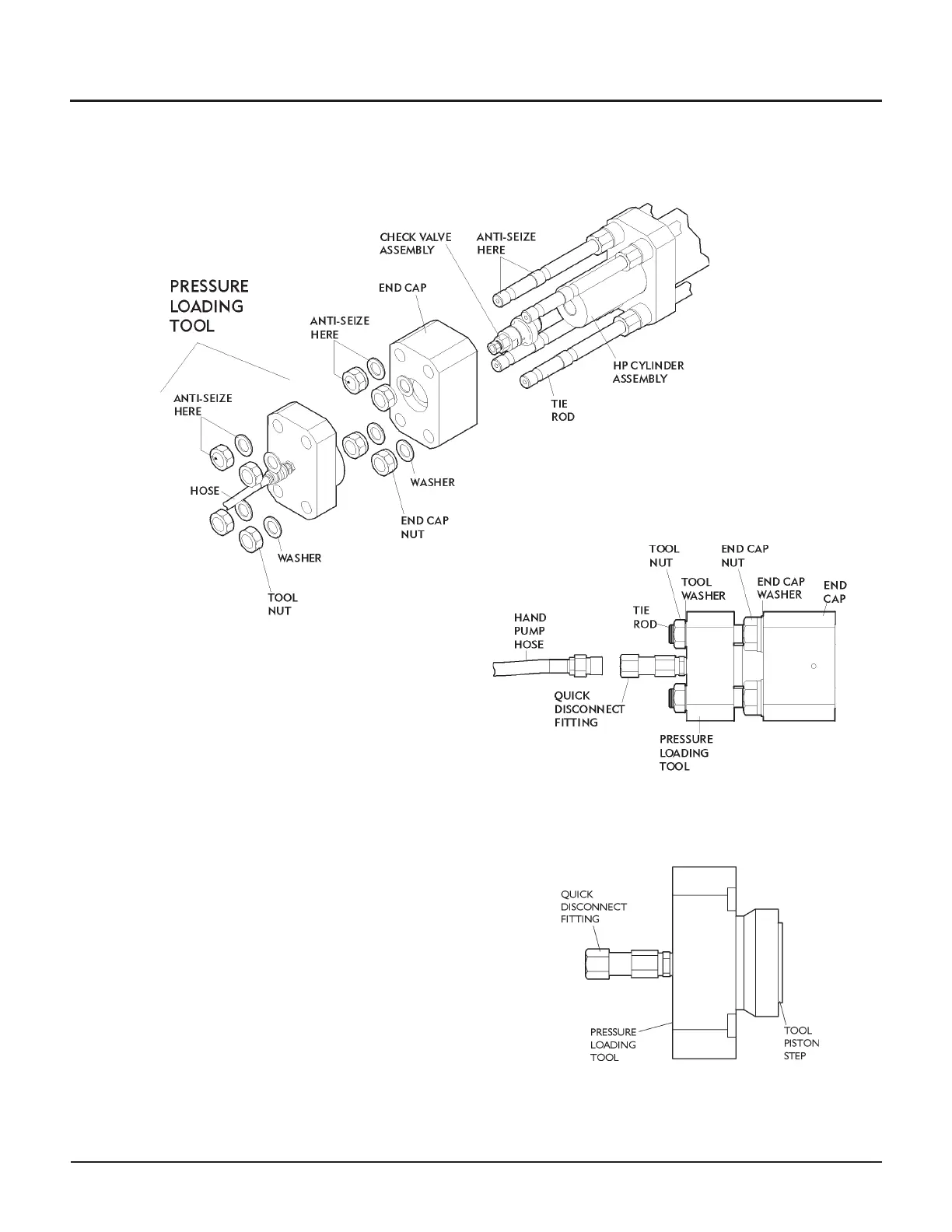
The illustrations on this page identify the parts used in
this procedure, and provide a visual description of how
the tool assembles to the tie rods of the intensifier.
1. Apply anti-seize (A-10039) to all exposed threads of
each tie rod. Apply anti-seize to the threads of the
end cap nuts and tool nuts and the contacting faces
of the nuts and their washers.
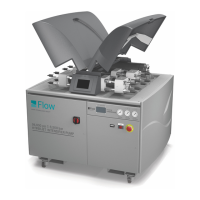
2. With the high-pressure seal assembly, high-pressure
cylinder, filler tube, check valve assembly, and end
cap in place, install the end cap washers and nuts on
the tie rods and run up hand tight to the end cap.
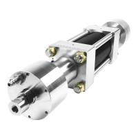
3. Install the tool on the tie rods and locate the tool pis
-
ton step in the end cap counterbore.
CAUTION
Make sure the tool piston step is fully engaged in the
counterbore before continuing. Failure to do so can damage
the end cap or the pressure loading tool.
4. Install the tool washers and nuts on the tie rod ends
and run up hand tight to the tool.
© Flow International Corporation M-376 | 19
CHAPTER 3
Maintenance Procedures