Maintenance Procedure F
Servicing the Low-Pressure Components
Tools required
Low-pressure assembly fixture plate (014030-1)
Torque multiplier
1½ in. socket (½ in. drive) and handle
1
5
8
in. socket (½ in. drive)
½in.drivetorquewrench
½in.driveratchet
1 in. open-end wrench
7
8
in. open-end wrench
13
16
in. open-end wrench
Slotted screwdriver
Check valve outlet replacement kit (014885-1)
Shift pin tool assembly (002228-2)
Rubber mallet
4x
3
8
-16 UNC threaded screws
Blue Lubricant (A-2185)
Food-grade grease (A-4689)
Anti-seize (A-10039)
Parker Super O-ring Lube (200006)
Service steps
1. Shut down the system.
WARNING
Place the main electrical disconnect in the OFF
position and bleed down the high-pressure lines.
Place an “Out of Service” tag on the main electrical
disconnect and lock it out. Failure to do so can cause
equipment damage or injury to personnel.
2. Disconnect the inlet water hoses from the end caps.
3. Using two wrenches, disconnect the high-pressure
tubing from the check valve outlet bodies. Loosen
the other ends and move the tubing out of the way.
4. Unload the intensifier high-pressure tie rods at
both ends of the intensifier.
•
See Maintenance Procedure A, Disassembling
the Intensifier
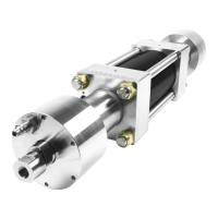
5. Note the orientation of the check valve body by ob
-
serving the position of the eccentrically positioned
outlet body relative to the intensifier. This is impor
-
tant when reinstalling the check valve body—correct
orientation is critical to ensure the correct fit of
high-pressure tubing, which is affected by the eccen
-
tricity of the outlet body.
Note: The check valve body is usually positioned
with the outlet body away from the intensifier mani
-
fold block, but this may vary on some intensifiers.
Check valve orientation of both the long-block and
short-block intensifiers is shown on the next page.
© Flow International Corporation M-376 | 47