Maintenance Procedure D2
Lappingthecheckvalvebodyfaceand
installing the inlet replacement kit
Tools required
½in.drivetorquewrench
¼in.drivetorquewrench
1¼ in. socket (½ in. drive) and handle
5
16
in. socket (¼ in. drive)
1 in. open-end wrench
7
8
in. open-end wrench
13
16
in. open-end wrench
5
16
in. open-end wrench
Lapping kit (B-1813-3)
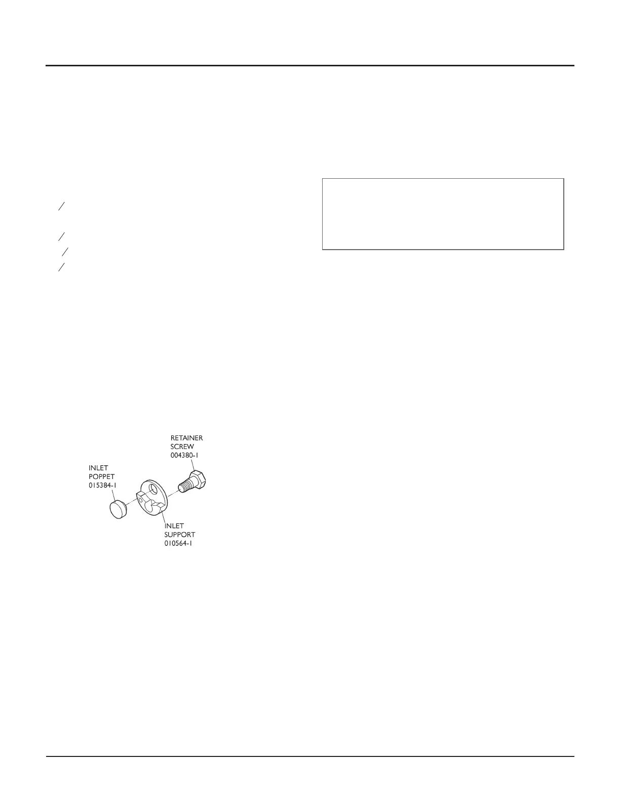
Check valve inlet replacement kit (014884-1)
Food grade grease (A-4689)
Blue Lubricant (A-2185)
Loctite #242 (A-3202)
Check valve inlet replacement kit
Service steps
1. Shut down the system.
WARNING
Place the main electrical disconnect in the OFF
position and bleed down the high-pressure lines.
Place an “Out of Service” tag on the main electrical
disconnect and lock it out. Failure to do so can cause
equipment damage or injury to personnel.
2. Disconnect the inlet water hose from the end cap.
3. Using two wrenches, disconnect the high-pressure
tubing from the check valve outlet adapter. Loosen
the other end of the tubing and move it out of the
way.
4. Using a 1¼ in. socket, loosen the outlet adapter
from the check valve body (do not remove it at this
point).
5. Unload the intensifier tie rods.
• See Maintenance Procedure A, Disassembling
the Intensifier
6. Note the orientation of the check valve body by ob-
serving the position of the eccentrically positioned
outlet body relative to the intensifier. This is impor-
tant when reinstalling the check valve body—correct
orientation is critical to ensure the correct fit of
high-pressure tubing, which is affected by the eccen
-
tricity of the outlet body.
Check valve orientation of both the long-block and
short-block intensifiers is shown on the next page.
© Flow International Corporation M-376 | 37
CHAPTER 3
Maintenance Procedures