Weep hole C
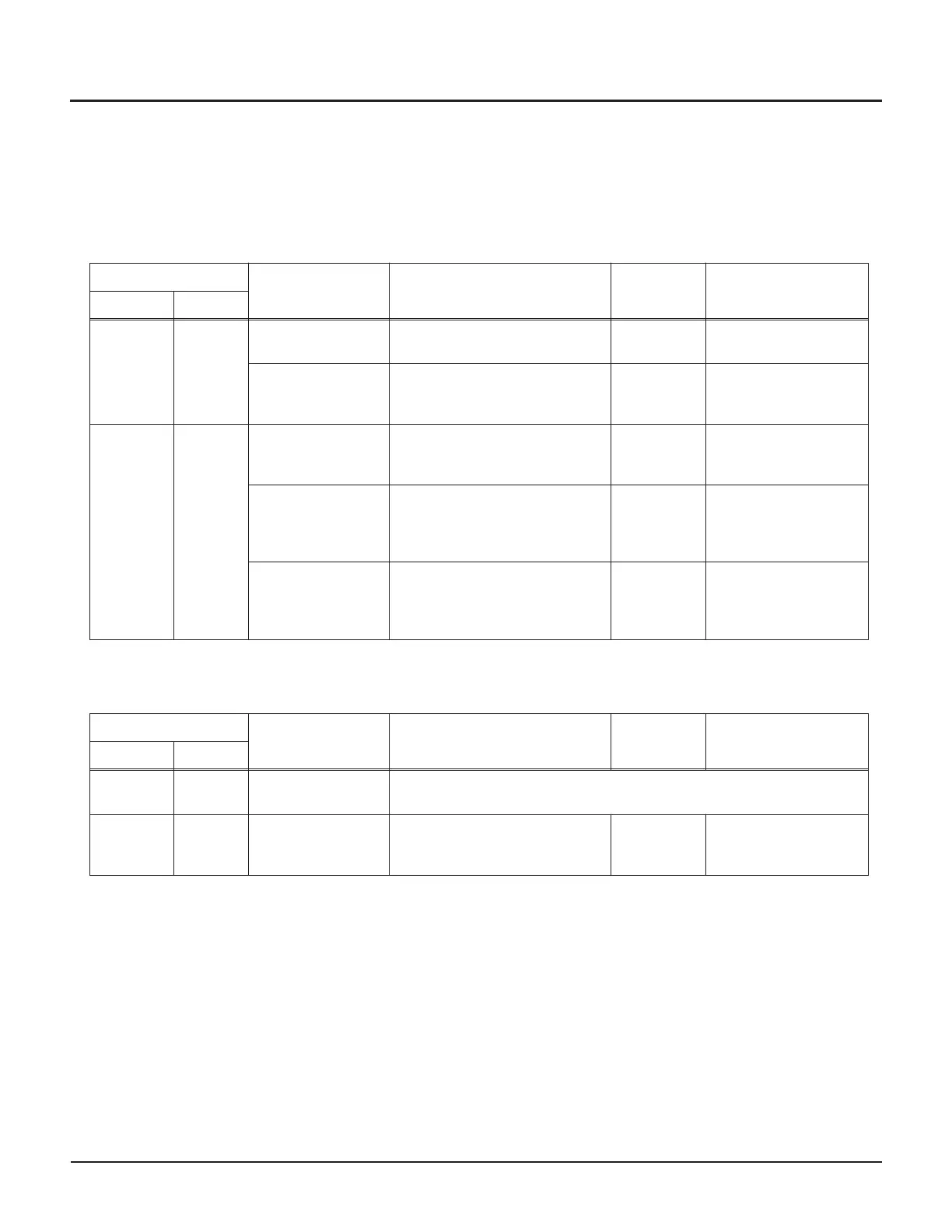
WATER LEAKAGE
Weep holes and locations are identified on the illustrations on Pages 64-65.
Note: Seal leakage is normal during intensifier operation. This normal leakage can start soon after new seal installa
-
tion, and does not damage intensifier components. A seal has failed and must be replaced only when the cutting
performance becomes unacceptable due to the drop in UHP water pressure caused by the seal leak.
Fluid
Likely problem Other possible symptoms
Maintenance
procedure
Kit or parts needed
Qty. Temp.
Steam with
each stroke
Hot/warm
Incorrect loading of
intensifier tie rods
Water leakage from A,B,D,E A —
High-pressure
cylinder failure
•
Pump cannot maintain pressure
•
Uneven intensifier stroking
A,C
High-pressure cylinder
020592-1
(2 per intensifier)
Large flow
with each
stroke
OR
energetic
leakage*
Warm/hot
High-pressure
cylinder failure
•
Pump cannot maintain pressure
•
Uneven intensifier stroking
A,C
High-pressure cylinder
020592-1
(2 per intensifier)
Seal carrier failure
•
Pump cannot maintain pressure
•
Uneven intensifier stroking
A,B
High-pressure seal
cartridge 052190-1 or
040015-1
(2 per intensifier)
High-pressure seal
failure
•
Pump cannot maintain pressure
• Uneven intensifier stroking
A,B
High-pressure seal
cartridge 052190-1 or
040015-1
(2 per intensifier)
OIL LEAKAGE
Fluid
Likely problem Other possible symptoms
Maintenance
procedure
Kit or parts needed
Qty. Temp.
Occasional
drip
Warm
Oil leakage from
hydraulic shaft seal
Note: a small amount of leakage is normal during operation
Small
periodic
flow
Warm
Oil leakage from
hydraulic shaft seal
— A,F
Low-pressure seal kit
013157-1 or 020080-1
68 | M-376 © Flow International Corporation
94K HYPERPRESSURE INTENSIFIER