58
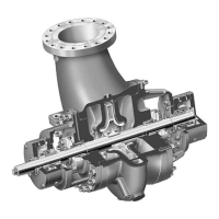
7. Place bearing housing in a horizontal position suitably supported. Fit new o-rings into the
grooves on each labyrinth. Working from the coupling end of the shaft the smaller labyrinth
over the shaft and press into the bearing housing until it locates against the machined
shoulder. It is held in place by the o-ring - no further fixing is required. Repeat the
operation for the other flinger, working from the impeller end of shaft.
8. Install coupling and pump end flingers onto shaft. Position flingers approximately 1mm
(.040") from their respective labyrinth and secure with appropriate clamping screws.
9. Fit new gasket in face of mechanical seal gland plate. Refit mechanical seal cartridge over
the 4 gland studs on the casing cover ensuring correct orientation of the gland tappings
(refer to mechanical seal assembly drawing). Secure with four nuts tightened to the torque
specified in section 7.12.
10. Rig bearing housing assembly to hoist impeller end and shaft downwards. Carefully lower
shaft end through seal sleeve until bearing housing locates on casing cover.
11. Secure bearing housing to cover.
12. Retighten mechanical seal drive collar set screws. Move setting plates from "transit" to
"run" position. Refit screwed piping into mechanical seal gland plates.
13. For non-inducer machines install key and impeller. Install locking nut - noting left hand
thread form. Torque nut to correct tightness. Fit and tighten lockscrew on end of locknut
throat bush (if fitted).
14. Install a new spiral wound gasket into position on casing cover.
15. Rig assembly with lifting straps to an overhead hoist and carefully install the assembled
pumping element into the casing.
NOTE
Use care when installing pumping element to avoid damage to the gasket.
Install nuts on casing cover to casing studs. Torque nuts evenly to correct tightness. (See Section
7.12).
16. Install coupling key and coupling hub onto the pump shaft.
NOTE
The coupling hub has a shrink fit to the pump shaft. The use of heat and an approved press/puller
will be required to install it. Install the pump half coupling hub by heating to approximately 300
degrees F (149°C) in successive stages from periphery of hub toward the centre. NEVER APPLY
AN OPEN FLAME TO THE COUPLING HUB TEETH.
17. If fitted install bolting holding to support plate to bearing housing and to baseplate.
18. Re-install drain plug and fill the bearing housing to the prescribed level with fresh
lubricating oil. (See Section 4).