13
Limitorque Actuation Systems L120 Series FCD LMENIM1201-04-A4 – 03/18
flowserve.com
c WARNING: Potential Explosion Hazard. Do not use a variable speed electric drill for setting the limit
switch in an explosive environment.
a CAUTION: When setting the limit switch rotor segments (cams) using a variable speed electric drill,
do not run drill at speeds higher than 200 RPM. Operating the drill at high speeds can damage the
gearing within the limit switch.
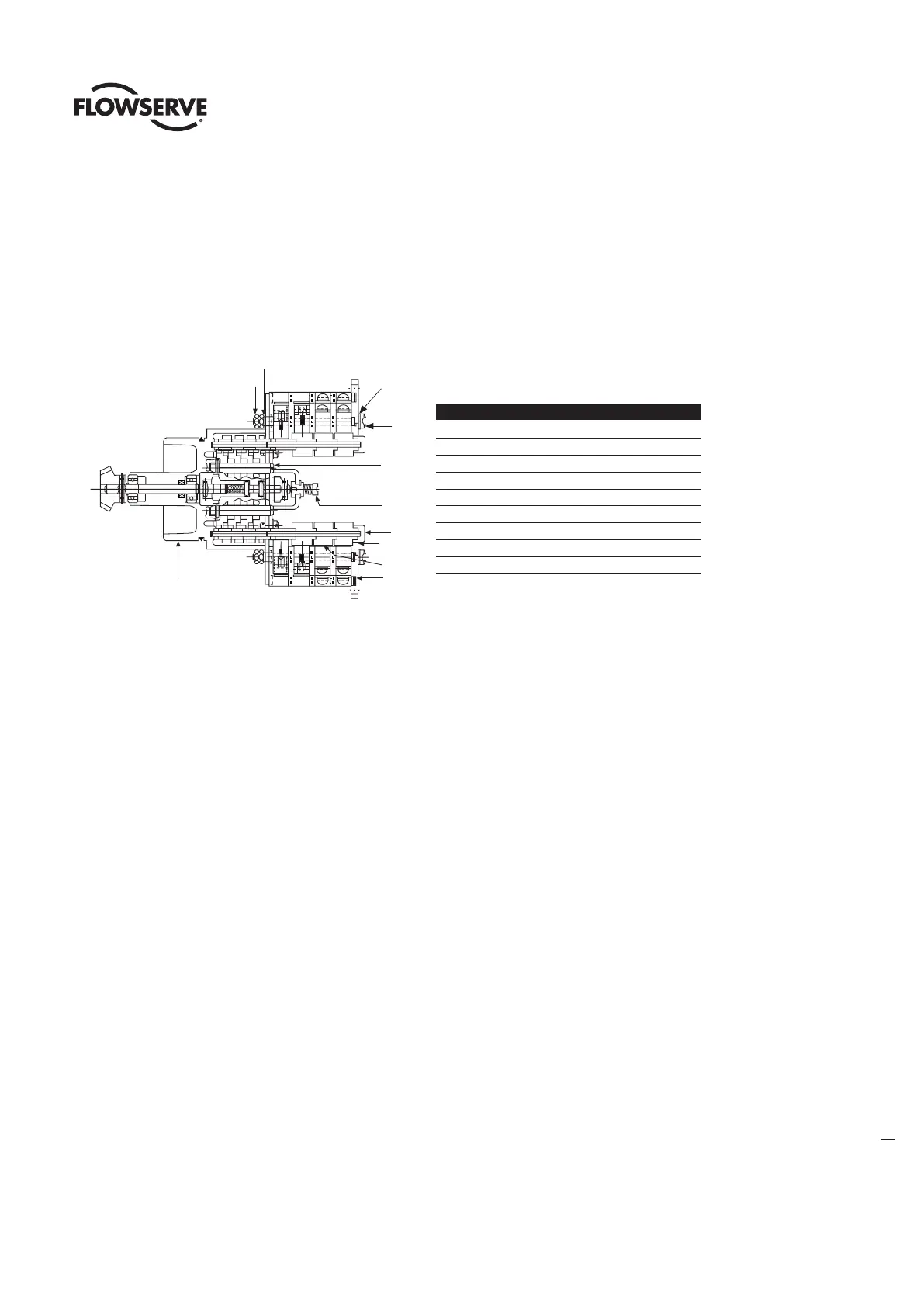
Figure 4.2 – Limit Switch
4.5.2 Setting Procedure (Refer to Figure 4.2)
1. Open the Compartment Cover (piece #200 of Figure 5.2).
2. Put the actuator into manual operation. Use the handwheel to operate the valve in the “open” direc-
tion. While operating the valve, note the direction of the Intermediate Shaft (B) corresponding to the
rotor or rotors to be set.
3. When the valve is fully open, close it one turn of the handwheel to allow for coast of moving parts
or refer to the valve manufacturer setting requirements.
4. Push in the Setting Rod (A) and turn one-quarter turn. The rod will latch in this depressed position.
5. Refer to the applicable wiring diagram for contact development. The limit switch contact is closed
when the rotor is engaged with the plunger. If the rotor to be set has not turned 90 degrees to
operate the plunger, turn the intermediate shaft in the same direction as noted in Step 2 until the
rotor clearly trips the switches. This rotor is now set correctly.
6. Before moving the valve, depress and turn the Setting Rod (A) one-quarter turn to the spring
released position. Insert a screwdriver into the intermediate shafts to ensure that they will not move.
a CAUTION: Do not operate the valve when Setting Rod (A) is in a fully depressed position. Loss of
contact setting will occur and the setting rod will be damaged.
7. Operate the valve by handwheel to fully “close” position; reverse direction by one turn of the hand-
wheel to allow for coast of moving parts or refer to the valve manufacturer setting requirements.
8. Set the other rotors by following Steps 4 through 6.
1
2
9
3
4
B
A
6
5
7
8
Piece Quantity Description
11 Gear Frame Assembly
22 Eight-Switch Contact Block Assy.
312Rotor Segment (short)
44 Rotor Shaft
54 Machine Screw
64 Flat Washer
74 Lock Washer
88 Hex Nut
94 Rotor Segments (long)