Logix 3200IQ Digital Positioner FCD LGENTB0059-01 – 10/09
6
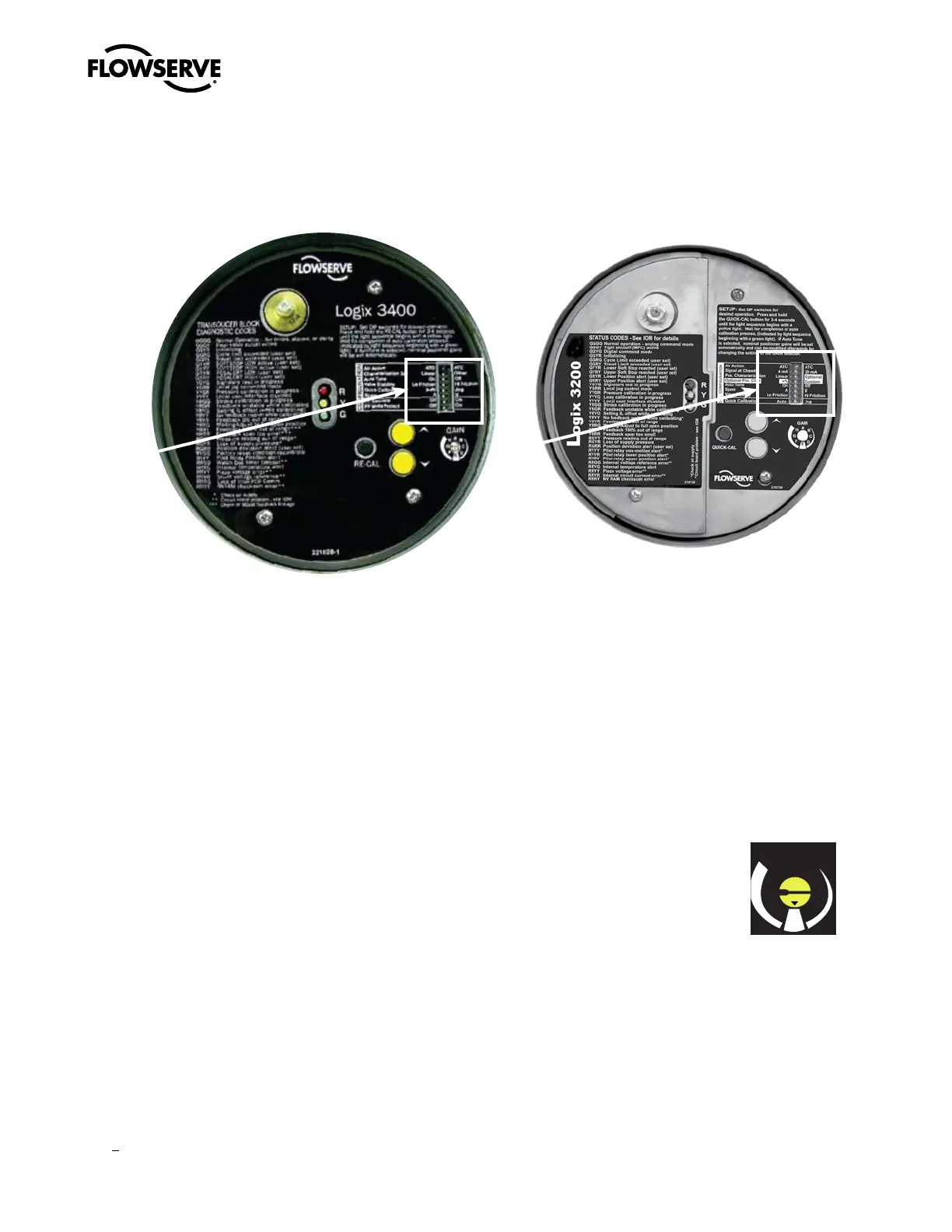
With the Logix 3400MD, function blocks are no longer
required to set up, configure and perform a simple stroke
calibration. The 3400MD can be set up with 9-32 VDC supply
and 45 psi (min.) air supply on any valve/actuator platform.
Calibration, configuration and tuning parameters from
the local interface will be automatically updated in the
Transducer Block on the Logix 3400MD. Local setup and
calibration that does not require a link to a host controller,
PC or hand-held device, as well as local validation that setup
is correct, make any F
o u n d a t i o n Fieldbus™ installation easy
and straightforward.
When the 3400MD is in OOS (Out Of Service mode), the local
interface shown to the right is accessible and setup can be
carried out through the following steps:
The Logix 3200MD can be set up with 10 VDC milliamp
current supply current and 45 psi (min.) air supply on any
valve/actuator platform.
Calibration, configuration and tuning parameters from the
local interface will be automatically updated in the HART
registers on the Logix 3200MD. Local setup and calibration
that does not require a link to a host controller, PC or hand-
held device, and local validation that setup is correct make
any HART™ installation easy and straightforward.
With the Logix 3200MD, the local interface shown to the
right can be used to set up the unit in seconds through the
following steps:
Common Configuration Steps
1. Make sure the mechanical linkage, air tubing and actuator mounting are correct.
2. Set the configuration switches to the desired operation of the valve/actuator.
3. Set the quick calibration switch to Jog or Auto. In Jog, the 100% position can be manually adjusted using the yellow up
and down buttons after Re-Cal is pressed. In Auto, the positioner finds the 100% position and calibration is complete. LED
blink codes will guide the user through the process. Four green blinks (GGGG) or (GGGY) at the end of the sequence confirm
that the calibration was successful.
4. If needed, the GAIN switch located to the right of the jog buttons will speed up or slow down the positioner’s response to
command changes. With the Auto Tune configuration switch set to “On”, the positioner’s algorithm will select a gain with no
over-shoot. The ‘E” position of the rotary GAIN dial indicates “neutral” with respect to gain adjustment. Turning clockwise
from E to H and will speed up the response. Tuning counter-clockwise from E will slow it down, with A being the slowest
response.
The Logix 3000MD Series Positioners – no software or hand-
held device required... easy as 1, 2, 3

 Loading...


