User Instructions - Logix® 520MD+ Series Digital Positioner
FCD LGENIM0105-00
© Flowserve Corporation 16 Field Trial Version – Printed October 28, 2011
7 ELECTRICAL CONNECTIONS
7.1 Electrical Terminals
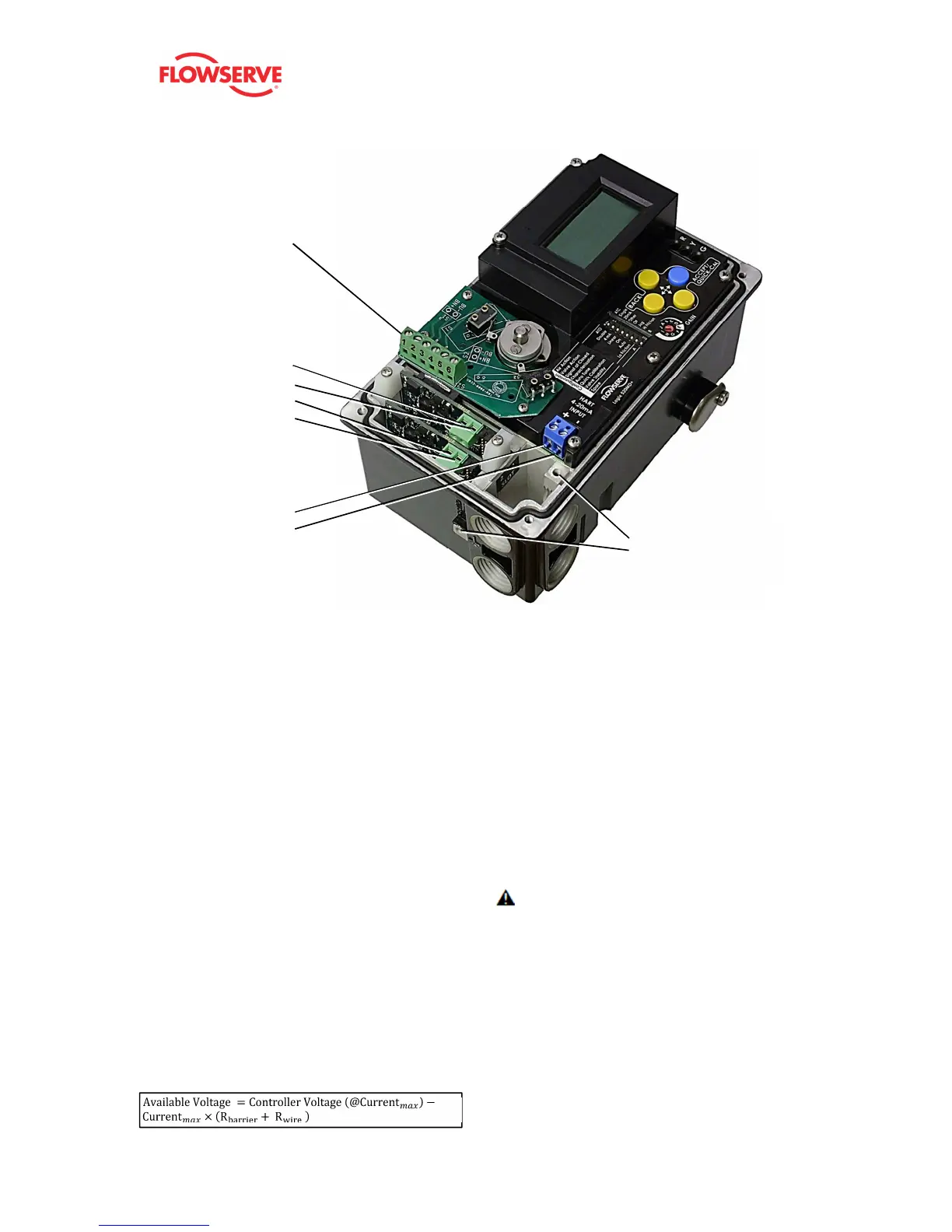
Figure 7: Terminal Diagram
7.2 Command Input (4-20 mA)
Connection
The Logix 520MD+ is reverse polarity protected, however,
verify polarity when making field termination connection.
Wire 4-20 mA current source to the input terminal labeled
“HART 4-20mA INPUT”. See
Figure 7: Terminal Diagram. Depending on the current
source, a HART filter may be required. See Figure 8: HART
Filter.
7.3 Compliance Voltage
Output compliance voltage refers to the voltage limit the
current source can provide. A current loop system consists of
the current source, wiring resistance, barrier resistance (if
present), and the Logix 520MD impedance.
The Logix 520MD+ requires that the current loop system
allow for a 10 VDC drop across the positioner at maximum
loop current. The operating current range is from 3.8 to 24
mA.
In order to determine if the loop will support the Logix
520MD+, perform the calculation in the following equation.
The Available Voltage must be greater than 10VDC in order
to support the Logix 520MD. Also, see Table 1: Input Signal.
Equation 1
Example:
The available voltage (12,5 V) is greater than the required
voltage (10.0 V) therefore, this system will support the Logix
520MD. The Logix 520MD has an input resistance equivalent
to 500 Ω at a 20 mA input current.
CAUTION: The current must always be limited for 4-20
mA operation. Never connect a voltage source directly
across the Logix 520MD+ terminals. This could cause
permanent circuit board damage
Limit Switch
Terminals 1-4 or
Terminals 1-6
Auxiliary Card