User Instructions - Logix® 520MD+ Series Digital Positioner
FCD LGENIM0105-00
© Flowserve Corporation 40 Field Trial Version – Printed October 28, 2011
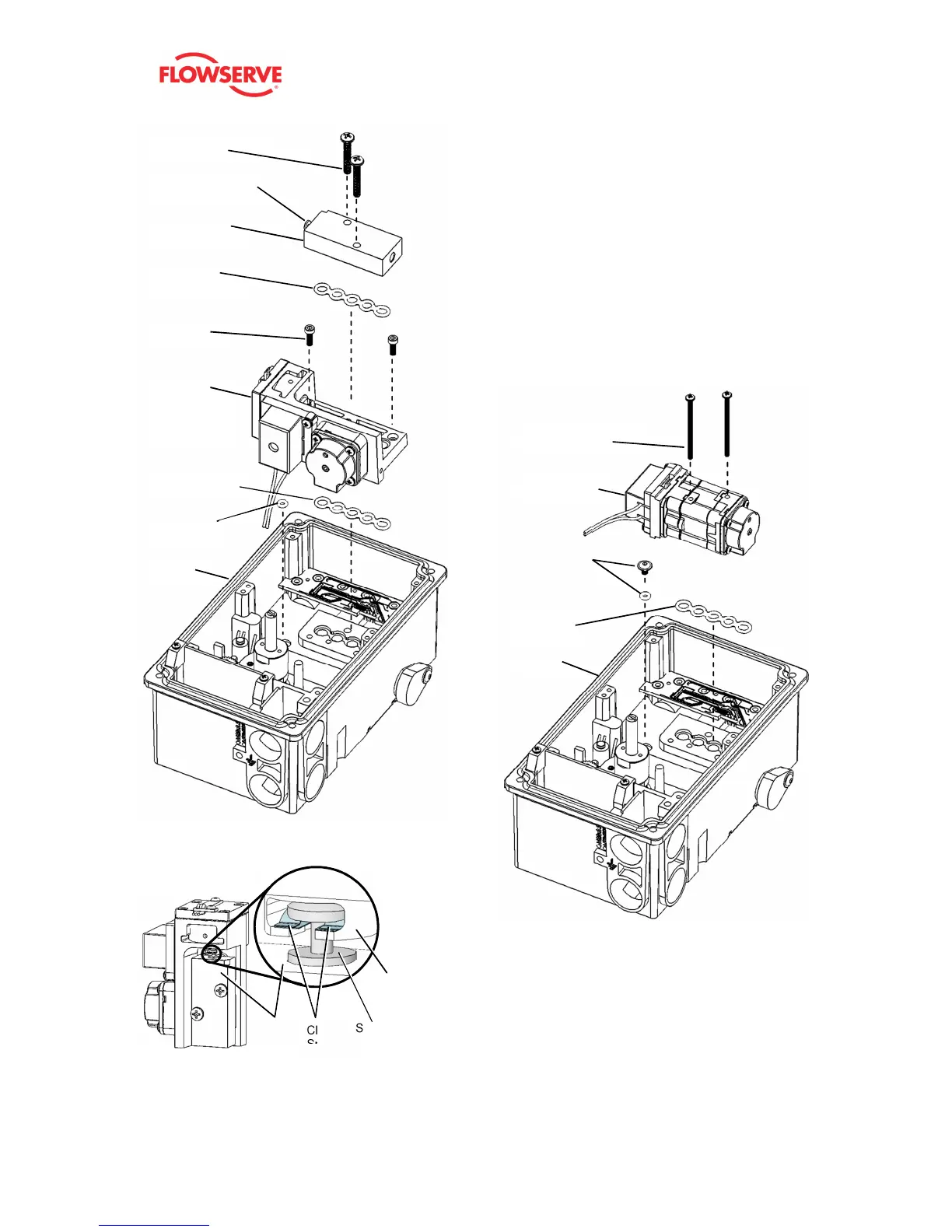
Figure 30: Double Acting Relay Assembly
Figure 31: Clip Spring Orientation
16.8 Replacing a Single Acting Pilot
Relay
Removal
1 Remove the Main Board. See procedure above.
2 Remove the two relay assembly screws.
3 Remove the single acting relay.
4 Remove the supply plug screw and o-ring.
5 Remove the Manifold gasket.
Installation
1 Place the Manifold gasket.
2 Place the supply plug o-ring and screw.
3 Place the single acting relay.
4 Place the two relay assembly screws.
5 Replace other components and calibrate.
Figure 32: Single Acting Relay Assembly
Spool
Clip
Spring
Block
Base
Double
Acting
Relay
Manifold
Assembly
Manifold
Screws (2)
Manifold
Gasket (2 of 2)
Spool/ Block
Assembly
Spool Block
Screws (2)
Manifold
Gasket (1 of 2)
Manifold
O-Ring
Spool and Clip