User Instructions - Logix® 520MD+ Series Digital Positioner
FCD LGENIM0105-00
© Flowserve Corporation 17 Field Trial Version – Printed October 28, 2011
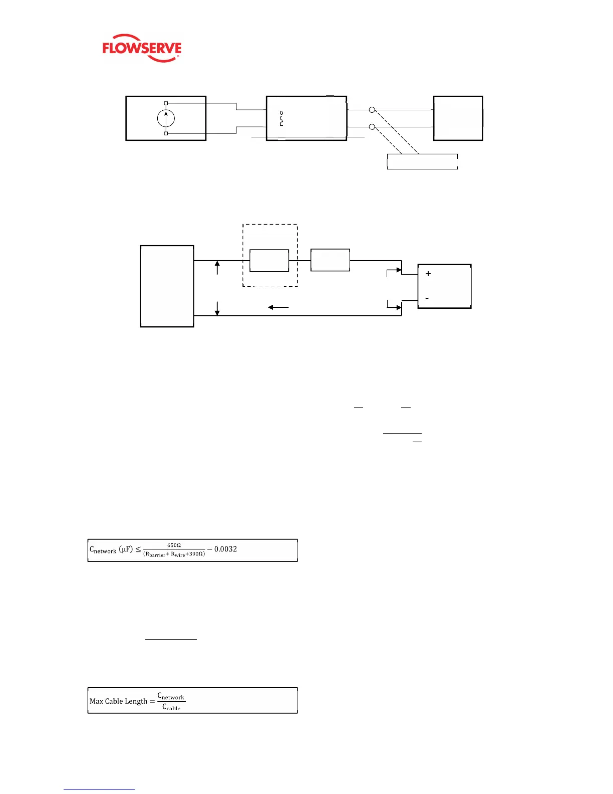
Figure 8: HART Filter
Figure 9: Compliance Voltage
7.4 Cable Requirements
The Logix 520MD+ digital positioner utilizes the HART
Communication protocol. This communication signal is
superimposed on the 4-20 mA current signal. The two
frequencies used by the HART protocol are 1200 Hz and
2200 Hz. In order to prevent distortion of the HART
communication signal, cable capacitance and cable length
restrictions must be calculated. The cable length must be
limited if the capacitance is too high. Selecting a cable with
lower capacitance/foot rating will allow longer cable runs. In
addition to the cable capacitance, the network resistance
also affects the allowable cable length.
In order to calculate the maximum network capacitance, use
the following formula:
Equation 2
Example:
(if present)
= 0.08
In order to calculate the maximum cable length, use the
following formula:
Equation 3
Example:
To control cable resistance, 24 AWG cable should be used
for runs less than 5000 feet. For cable runs longer than 5000
feet, 20 AWG cable should be used.
The input loop current signal to the Logix 3200MD digital
positioner should be in shielded cable. Shields must be tied
to a ground at only one end of the cable to provide a place
for environmental electrical noise to be removed from the
cable. In general, shield wire should be connected at the
source, not at the positioner.
7.5 Grounding and Conduit
The grounding terminals, located by the electrical conduit
ports should be used to provide the unit with an adequate
and reliable earth ground reference. This ground should be
tied to the same ground as the electrical conduit. Additionally,
the electrical conduit should be earth grounded at both ends
of its run.
The grounded screw must not be used to terminate signal
shield wires.
This product has electrical conduit connections in either
thread sizes 1/2" NPTF or M20x1.5 which appear identical
but are not interchangeable. The thread size is indicated on
the side of the positioner near the conduit connections.
Conduit fittings must match equipment housing threads
before installation. If threads do not match, obtain suitable
adapters or contact a Flowserve representative. See Figure
10: Conduit and Grounding.